The Creeper Cranes.
The arch span of the Sydney Harbour Bridge was erected using two cranes which were aptly named ‘Creeper Cranes’ as they moved forward onto the bridge truss that they had just built to create the next panel, until the half arches met it the middle of the span. While the general concept of this procedure is well known among admirers of the bridge, the details of the scheme evolved through the design process. The cranes which ultimately did the job were remarkable machines.
It was by no means necessary that a single crane (or two cranes – one on each half span) would carry out the whole task. David Anderson, whose firm had designed the Tyne Bridge in Newcastle UK, built simultaneously with the Sydney Harbour Bridge by Dorman Long, commenting on Freeman’s and Bradfield’s papers on the work, delivered to the British Institution of Civil Engineers in 1934, pointed out that that bridge had been built using a 5-ton derrick-crane which built a 20-ton derrick-crane which built the bridge and lifted the smaller crane ahead to move the larger crane to a new position to erect more of the bridge. He thought that the Sydney creeper cranes were expensive and must have set up heavy bending stresses in the bridge trusses. Freeman replied that the cranes were indeed expensive - £45,000 in the UK and £50,000 by the time they were erected in Sydney, but that the great width of the Harbour Bridge in relation to its panel length made the leap-frog technique impossible. The bridge structure had been designed to carry the erection loads imposed and in retrospect he thought that the cranes were perfect appliances. They had done every duty that had been imposed on them without a hitch from beginning to end and if the same problem had to be faced again he did not know a better way of dealing with it.[1]
The draft erection procedure for the bridge as it existed in March 1924, when Dorman Long’s tender had just been accepted, included a creeper crane, slightly less in weight (536 tons) than that actually used but of much greater in lifting capacity (160 tons). It would have been employed as far as the tenth panel of the fourteen in the half arch only. A much lighter crane (180 tons), perhaps a stiff leg derrick crane, would have been used for the last four panels and apparently the erection of the deck. The prospect of having a 600-ton crane at the end of an 825-foot cantilever was not one to be glossed over.
An article in The Sydney Mail on 26 March 1924, written by Kathleen Butler from the notes of J. J. C. Bradfield, includes the words:
The cranes weigh 536 tons each, and have been specially designed for this work, to lift members up to 160 tons weight.
In the fourth stage, as soon as sufficient cable is provided to sustain the reaction, the cables secured to the end post will be slacked, and the crane will continue to erect successive panels until the tenth panel is reached, leaving four panels on each side of the centre-line to be erected.
The remaining panels will be erected by means of a lighter crane, whose total weight is only about, 180 tons.
The accompanying drawings in the articles, sketchy as they are, illustrate these concepts. They are presumably sourced from Dorman Long as the publication date is only two days after the signing of the contract.
With hindsight it is easy to ask how the light crane could have lifted the deck cross girders which were among the heaviest lifts on the bridge, but that would be to second guess the evolution of the design and the arguments that were had between the skilled and experienced men who carried out the work.
The final design was to use a 600-ton machine with a lifting capacity of 120-tons all the way to the centre of the span to erect the arch and then on its return trip to erect the deck. Heavy and expensive as they were, two cranes were manufactured. Much of the other gear for the bridge erection was moved back and forth across the harbour so as to make double use of only one set, but this was not possible for the cranes.
The creeper cranes were built specifically for the job in England by The Wellman Smith Owen Engineering Corporation Ltd. of Darlaston and one was erected on a stage approximating the slope of the Bridge top chord in Middlesbrough for testing before shipment to Sydney.
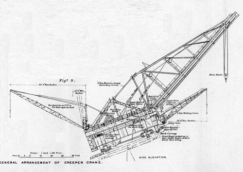
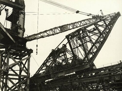
The machines were much more than a single high-capacity crane. They had five independent cranes carried on the same chassis.
The main crane – the one which would lift the heaviest components of the bridge – had a capacity of 120 tons. It could derrick, that is move the point of lift forward and back, under full load, by means of two large (9 inch) screws moving in phosphor-bronze nuts built into the crane jib, and could traverse across the width of the bridge to 25 feet beyond the arch trusses, on a track 148 feet long. The extreme point of lift was 10 feet outside the edge of the main truss and the speed of lift for maximum loads was 12½ feet per minute, meaning that a lift from a pontoon on the harbour to the higher parts of the bridge would take half an hour. Twice this lift rate was available for lighter loads up to 65 tons. The crane could traverse with a full load at 30 feet per minute, though this was automatically reduced to 10 ft. per minute at the ends of the travel.
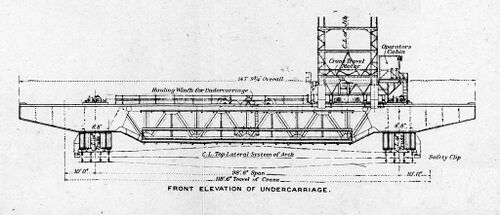
The traversing carriage was supported on a heavy box section underframe spanning between the bridge trusses and cantilevered beyond them. For travelling, the underframe was supported on four four-wheel bogies with unflanged wheels running on the flange plate of the chord directly above web plates inside the section. Once in position the front bogies were relieved of load using powered screw jacks.
The carriage was hauled along the top of the bridge by a winch driven by a 50 H.P. electric motor through cables attached to points in the top chord at the further end of the panel just erected. The anchorage used was a keep plate grooved to clear rivet heads and secured through an access manhole in the flange of the box section bridge chord. Advance was at a speed of one foot per minute, or about an hour to advance one panel.
The carriage was fitted with guide rollers on the outside of the flanges and clips locking it against overturning. Mechanisms were in place to ensure that both sides of the undercarriage moved forward at the same rate. The greatest worry however in the moving process was that a failure of the winch or cables could result in the heavy mass falling back until some check mechanism cut in. It was considered that the impact of the 600-tons falling one inch would result in the complete loss of the half truss and however remote, this was not acceptable. To avoid the possibility of any slip the moving undercarriage was also secured by four heavy link-and-pin chains, a pair on each chord, around a sprocket at the outer end of the chain. An electric motor driving though a worm gear maintained a tension force in the chains and had the weight of the crane fallen on to them there would have been minimal movement before they held the full load.
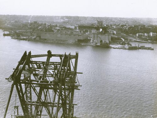
There was only one set of chains and tensioning mechanism, and it was moved between Dawes Point and Milsons Point for the relatively infrequent movements of the cranes. The inclination of the top chord was a challenging 1 in 2 at its steepest but as it reduced with the curve of the arch and the cranes reached the flatter part, after the eighth panel, a simpler mechanism was used with a single chain with two pawls, one of which was always engaged. The attachment of the chain to the bridge after the eighth panel was a simple pin.
For the return journey of the cranes once the two halves of the arch had been joined, the motor, worm and sprocket mechanisms were left in the centre of the bridge and the chain extended successively with panel-length sections of cable for each movement. The chain was run through the machine to the north or south side as the respective cranes were lowered.
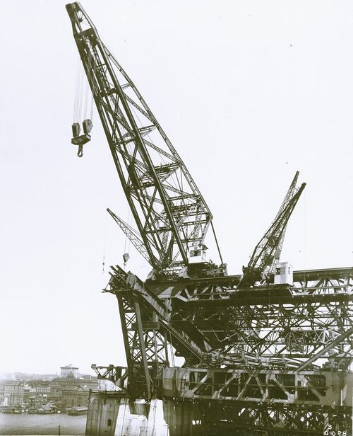
Beneath the jib of the main crane was a trolley carrying the lifting point for the jigger crane. This had a capacity of 20 tons. It traversed with the main crane, but its point of lift could move along the length of the main crane's jib. Its main purpose was as a supplementary point of attachment to loads to control their inclination. Although in major lifts it hoisted at the same rate as the main crane, it could also independently lift lighter loads at twice the speed. Both hoisting and traversing were driven by 50 H.P. electric motors. Under full load the trolley could traverse the full length of the jib in two minutes.
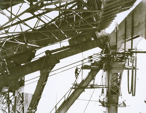
Along the front girder of the crane undercarriage a 5-ton wall crane operated independently. Its travelling capacity was 50 feet and by using both this and the slewing capacity of its 39-feet jib, it could reach any point in the bridge width. It had a hoisting rate of 60 ft. per minute and could traverse the whole length of its track in a minute. It was used for movement of stages and workers.
A frame attached to the back of the traversing carriage supported two 2½-ton derrick cranes with 70-feet jibs for dealing with riveting stages, stores, tools, etc. The frames for the cranes were adjustable to allow for the angle change as the main crane travelled up the arch, and they could reach any point in the preceding panel and lift at 40ft. per minute.
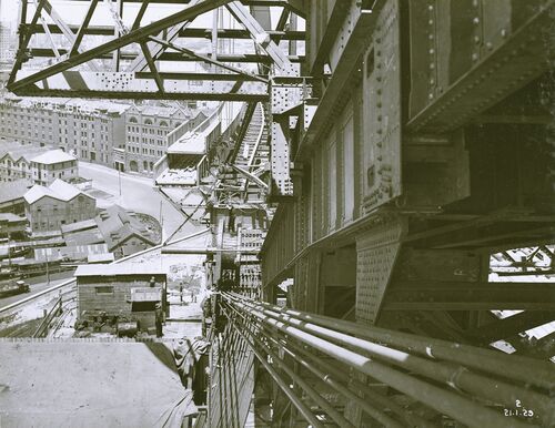
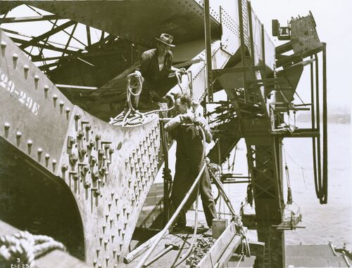
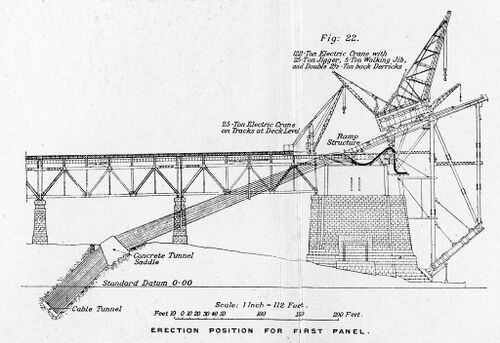
The five-cranes-in-one machines were erected on the deck level of the abutment towers by the 25-ton derrick cranes which had built the approach spans. The creeper cranes were erected on temporary ramps at the same inclination as, and aligned with, the top chord of the truss which they would build. Their first task was the erection of the end panel of the bridge. The usual path from workshops to crane hook was via a barge, but at Dawes Point the creeper crane, standing on the pylon could not reach the harbour side so the floating crane ‘Titan’ lifted components from barge to shore and within reach of the creeper crane. At Milsons Point ‘Titan’ was not required as sections were brought directly from the workshops by rail.
With the end frame erected the crane ramp was extended to it and the crane moved forward to a point where it could erect most of the first complete panel, before moving forward again to erect the cross members in the lateral bracing system. The ramp occupied the position where the permanent cable anchorages for the half-truss would eventually be and so a temporary tie-back point was made lower on the end post.
With the first panel complete the creeper crane moved fully onto it, the ramp was dismantled and taken to the northern side of the harbour to repeat the process. This allowed the permanent tie-back arrangements to be set up at the end of the top chord.
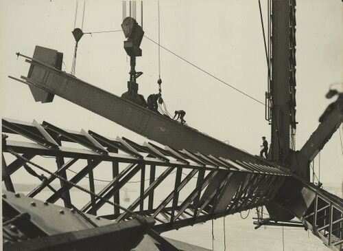
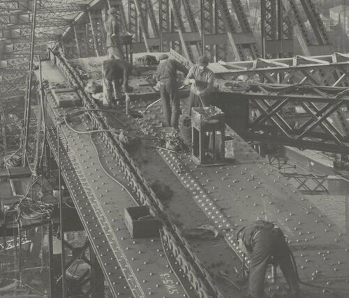
Erection of the next thirteen panels on each side of the harbour was a repetitive process with the crane erecting a panel and then moving on to it. The southern half arch was built in advance of the northern, but at panel 8 the southern work stopped to allow the northern to catch up and for them to then advance together.
On their outward journey on the steepest parts of the top chord the cranes were able to lift 122 tons at 41 feet in advance of the panel point on which they were standing and 65 tones at 61 feet ahead. On their return journey they needed to be able to lift the 100-ton deck cross-girders and on the near horizontal upper parts of the curve could not derrick sufficiently to a radius short enough to lift this load. This required the derricking range of the jibs to be adjusted. Provision had been made for this in the design by allowing for some members of the jib truss frame to be removed.
Freeman and Ennis write:
It had been anticipated that this process would be somewhat hazardous and difficult, because until the two cranes met at the top of the bridge they had always been regarded as independent, and while they were so the change-over would certainly have been a very anxious undertaking. The change was, however, conveniently carried out at the centre of the bridge, the jibs of the two cranes being allowed to rest against each other while the back members were removed.[2]
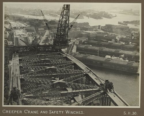
For the erection of the deck there were inherent limitations with the cranes now above the completed trusses. The deck cross-girders were directly below cross-members in the bracing in the planes of the upper and lower chords. This could be worked around with relatively light tackle, but a more challenging problem was the deck hangers which were directly below the chords and quite inaccessible to the crane hook. A frame for hoisting and rotating the slender sections was devised and this allowed them to hang perfectly vertically, offset from the crane hook by half the width of the chord.
A number of pieces of the deck structure were situated outside the reach of the creeper crane and, to place these in position, a pair of railway stringers braced together, forming a box 60 ft. long and 7 ft. 6 in. wide, was used as a horizontal lifting beam. This beam was slung by means of four straps in an unbalanced position and the members to be lifted were attached to the light end; with the addition of this weight the lifting beam assumed a position practically horizontal and the member to be lifted could be placed into position some distance from the hoist. This lifting device was adopted for the chord members of the deck lateral system, the footway spans, and the painting gantry girders beneath the arch ribs.[3]
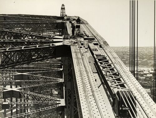
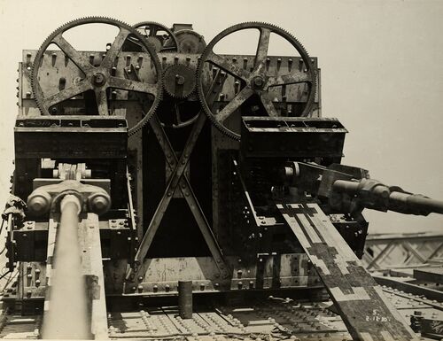
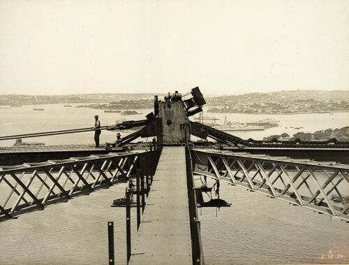
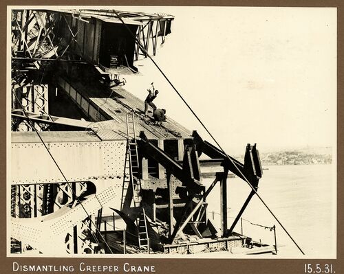
By the time that the creeper cranes had returned to the ends of the main span the 25-ton derrick cranes from the approach span erection had gone and the concrete and stone pylons were being erected by 7-ton cranes on 80 -feet high timber towers. These smaller cranes re-erected the 25-ton cranes including an extended jib, on similar timber towers, also 80 feet above the deck. The 25-ton crane dismantled the creeper crane and then the 7-ton crane dismantled the 25-ton crane.
Sources
Sydney Harbour Bridge, Dorman Long and Company Limited 1932
Transactions of the Institution of Civil Engineers 1934. Papers by Ralph Freeman, Lawrence Ennis and John Bradfield.
Sydney Harbour Bridge Photograph Albums. NRS 12685. NSW Museums of History.


