Logistics of concrete placement in 1923
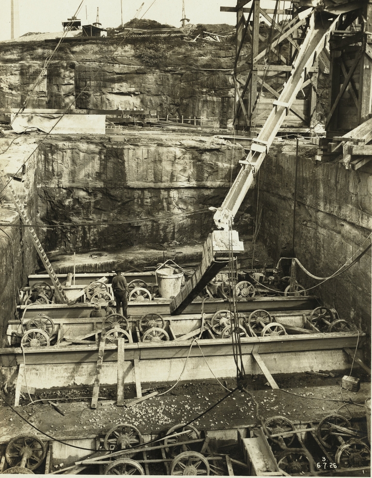
At the time of construction of the Sydney Harbour Bridge and it approaches the concrete supply industry had not developed. There were no permanent batching plants supplying concrete to order and no transit trucks to deliver mixed concrete to sites. For structures well above ground level such as the Harbour Bridge abutment towers cranes could used to lift hoppers, but in other cases hoist towers carried the concrete to great heights to allow further distribution by gravity. For ground level works the common method of delivery was by gravity using long and sophisticated chutes, sometimes from an elevated batching plant. The design of a concrete structure thereby required considerable extra design and construction to establish a delivery path for the concrete.

Delivery of concrete for mined railway tunnel roofs was by rail-mounted skips, with the final placement done by manual shovelling. Very late in the period of construction concrete began to be delivered by concrete guns, especially to remote tunnel sites. These machines were properly ‘guns’ rather than pumps as they required a relatively large chamber to be filled with concrete and sealed air-tight. Compressed air then introduced to force the contents of the chamber through pipes in a single pulse. The chamber was then opened and refilled.
On the City Railway at least one fatal accident resulted from an attempt to clear a blockage without disconnecting the firing mechanism.
Cement was always supplied in bags, rather than in bulk, and the bags weighed one hundredweight, (112lbs or 50kg). In preparation for a big pour huge stockpiles of bagged cement were accumulated at the mixer and covered with tarpaulins pending the start of work.
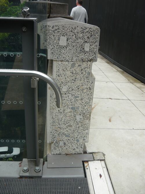
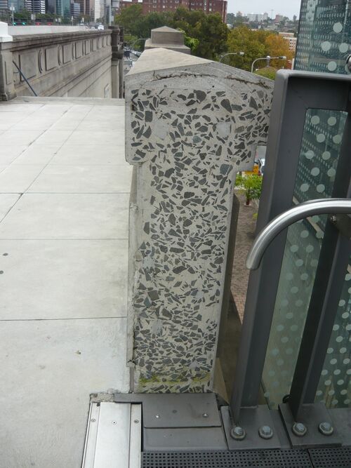
Much of the concrete used, especially for mass concrete applications such as foundations, was specified as ‘sandstone’ concrete – that is, concrete with crushed sandstone as the aggregate. More intensively loaded applications used crushed hard igneous rock to produce ‘bluestone’ concrete. The Dorman Long and Co sections of the Harbour Bridge – the abutment towers, skewbacks and approach span piers, used crushed granite as the aggregate. This was a by-product of the quarry at Moruya which was producing cut stones for the abutment towers and pylons.
In late 1923 we have a snapshot of the batching equipment available given in Bradfield’s DSc(Eng) thesis. It comprised one 16 cubic foot (about 0.5 cubic metre) steam driven “Foote” mixer and three 10 cubic foot (about 0.3 cubic metre) electrically driven “Armstrong-Holland” mixers. Three 10 cubic foot electrically driven “Foote” mixers were on order at that date.
In the 1920s large construction projects did not have long reach cranes covering the whole site, so the delivery of mixed concrete to a wide site such as Museum or St James station involved long runs of chute supported by cables and tackle from the higher ground above the excavation. Elaborate articulations were built into the chutes to allow redirection to the place of use.
Bradfield discusses these in his thesis and states that the design
giving the most satisfactory results being the imported “Insley” Chute. This chute is of a deep parabolic section, about 12 inches wide, by 13 inches deep [300 x 350mm], and is obtained in lengths of 10, 20 and 30 feet [3, 6 and 9m], provided with suitable hoppers, swivel heads and plates.
In locations where tunnels were below roads or parks, 6-inch (150mm) holes were bored from the surface, the batching plant established in the park or the middle of the street above and the concrete delivered directly to the space behind the formwork deep below. Men worked in the space spreading and packing the concrete. This was eminently possible as most concrete was not reinforced, or only reinforced very lightly. On the Harbour Bridge the piers of the approach spans are of plain concrete only, and the more than a metre thick walls of the abutment towers have horizontal reinforcement only – two ⅞ inch (22mm) bars, one near each face, at 18-inch (450mm) centres! (Freeman ICE Journal 1934)
Just before work began on the City Railway and the Bridge there had been another immense concrete project in Sydney – the Glebe Island wheat silos, and there the placement of concrete by gravity had been taken to its logical extreme. To serve a huge slip-form, concrete was hoisted to a great height in timber towers and then allowed to flow to all corners of the many cylindrical silos by a switchyard high above the form.


