Closing the Arch.
The steel-truss arch was a late starter in the design of the Sydney Harbour Bridge. Cantilever designs were previously preferred because there was no doubt that they could be built – The Firth of Forth railway bridge had been built with two spans longer than that needed in Sydney more than 30 years before. The technique of building half arches as cantilevers, tied back with cables, had been used before over the Zambesi River at Victoria Falls in 1905 and Hell Gate in New York in 1916, but both bridges were much shorter in span and very much lighter than any Sydney Bridge.
The engineers of the 1920s took a bold leap in technology when they dared to attempt a 1,650 feet (502m) arch.
To ensure that there would be space in the centre to place the last members of the trusses as the halves reached out to each other, both half arches were built slightly too far back – and slightly for an 825ft cantilever is 30 inches (750mm) in the height of the tall end post. The design calculations gave the figure of 40 inches (1 metre) for the gap in the middle when both halves were complete. This presupposed great care in the manufacture and also the accuracy of the complicated calculations of deflection. With section sizes and forces unprecedented in engineering, room for error had to be allowed. The long-term creep behaviour of the cables was also uncertain.
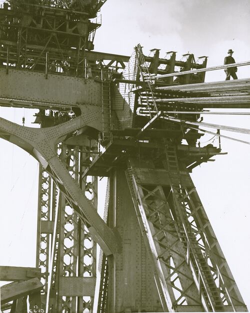
Thus, it was always necessary for the two half arches to be lowered until they met, and an elaborate mechanism was built into the structure to allow this to happen. This mechanism – lengthening the tie-back cables – was not the only option. An early design carried the cables over a tall strut erected on the end post. The lowering would have been achieved by shortening the strut. It would also be perhaps necessary to raise or lower each half truss, or re-aim them, if they were not in close alignment.
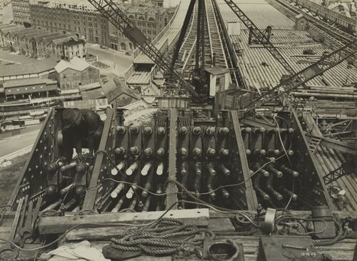
When the half arches met, 128 cables were attached to each half truss at the end of the top chord. They carried a force of about 14,000 tons and were in one piece through deep tunnels in the sandstone well behind the shoreline. Each end was terminated in a cast steel socket which connected to two long 3 1/16 inch bolts. These bolts carried a saddle which loaded onto an 11-inch pin held within a link plate which connected to the bridge. The bolts loaded the saddle through nuts. The bolts extended 32 inches beyond the nuts to allow the fitting of a second saddle. If need be, the bolts could be lengthened with sockets and 25 inch extension threads.
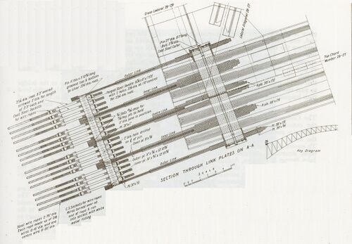
Between the two saddles there was space for a hydraulic jack which could load onto the outer saddle. Dimensions were tight so the jack was physically small in diameter and the operating pressure needed to be high. With the jack taking the force in the cable, the nuts against the saddle on the pin could be moved and the cable lengthened, or shortened, with a consequent change of the force in the cable. Four power-operated[1] pump jacks were used at each anchorage, co-ordinated so that while one was releasing a cable the others were being moved and set up. The sequence of work was controlled to ensure that the same cable was adjusted at both ends at the same time and spread across the 128 to avoid loading the link plates to the bridge asymmetrically. The cycle to place, load, release and then relocate took at first about 20 minutes, but as the workmen operating the plant became accustomed to the task they completed an operation in about 15 minutes, or 40 to 50 operations at each end post in a day, moving the end of the truss about 4 inches (100mm).
Obviously as the half arches were erected a careful check was kept of the position of their ends, compared to design. This was a difficult measurement as the half arches were exposed to uneven temperature changes. At their greatest length, heating and cooling from day to night caused a change in length about 4 inches (100mm). The bridge being basically north-south, the morning sun warmed the eastern truss, lengthening it, and then the western truss extended in the afternoon as the eastern truss cooled, thus swinging the bridge east and west. The northern half arch geometrically presented more area to the sun for heating. The half arches were also moved in the wind. The task of surveying the position of the end of construction, at least from the NSW Public Works Department point of view, fell the Roger Butler.[2] Butler was a young [3] locally trained engineer, like most of Bradfield’s staff. Dorman Long kept their own check on the location of the last member erected. The men named by Freeman and Ennis as the survey staff were RH Blake, DS Lawrence and J Muir, though their responsibilities also included substructure, concrete and masonry. Difficulties in obtaining reliable measurements increased as the half arches lengthened.
Despite all the noise, no deviation of the southern half arch could be detected. On the northern side of the harbour there was a consistent tendency for the end of the half arch to move westwards and it was decided to correct this at the ninth panel point. The end of the structure was estimated to be 1 1/16 inches (27mm) too low and 1⅛ inches (28mm) to the west. This was corrected by running out the cables of the western anchorage ½ inch (13mm) and taking in the cables of the eastern anchorage by ¼ inch (6mm). No further adjustments of either half arch were required.[4]
No explanation of the movement was ever proved, though it was noted that the northern tunnels were particularly damp with seepage, and those in charge of the work believed that the stretching of the cables was greater on the east side than the west.
When the final members of the lower triangles of the fourteenth panel of the half arches were erected the gap was measured to be ‘about 36 inches’ (900mm)[5] by Dorman Long, and either 2 feet 7½ inches (800mm) varying considerably with temperature, or 3 feet 7 inches (1100mm)[6] by NSW Public Works, depending which paragraph is taken as correct on Page 366.
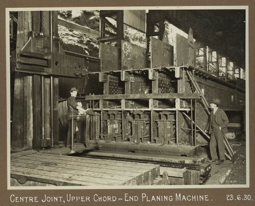
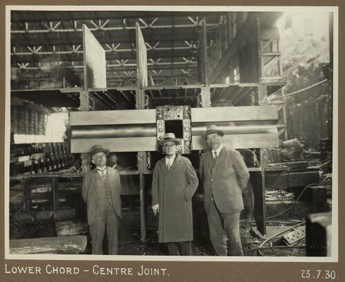
All joints between members of the half arches were pre-assembled in the workshops before being erected in the bridge, so the precision of the joint was assured, but for the joint between the two halves a near perfect joint could not be assumed. This risk was circumvented by joining on 8-inch pins between two heavy forged saddles. The force in the arch at the crown would thus be axial and safely spread across the section.
At the commencement of the lowering the northern half arch was 5 inches west, though varying with temperature. To ensure perfect alignment on meeting a 10 inch (250mm) square pin with a tapered end was lifted with the last chord members of the southern arch, with a corresponding hole in the northern arch. Once engaged it was strong enough to force the opposite cantilever into perfect alignment on the circular pins in the saddles.

A start was made with the erection of the fourteenth panel on the south side on 4 August 1930, and on the north side on 7 August. The panel was completed on the south side on 8 August and on the north on 12 August. Operations for lowering the half arches commenced a day in advance of the completion of the panels on 7 and 11 August respectively. The original 30 inch rake of the end posts had been reduced to 18 inches and 16½ inches south and north by the weight of the erected steelwork stretching the tie-back cables.
The release of the 128 cables at each end post was limited by the 130-ton capacity of the jacks employed. Each cable carried a force of 108 tons. When the first was slackened by 3 inches the force in it was reduced to 88 tons while the other 127 cables stretched 3/128 inch, the post moved 1/40 inch and the end of the half arch 1/20 inch. After all but one cables had been released 3 inches the last cable would be stretched 3 inches and be carrying a force of 128 tons, just less than the nominal capacity of the jack. The 4 tons per square inch operating pressure in the jacks was increased up to 4½ tons for the later stages of the cable release process.
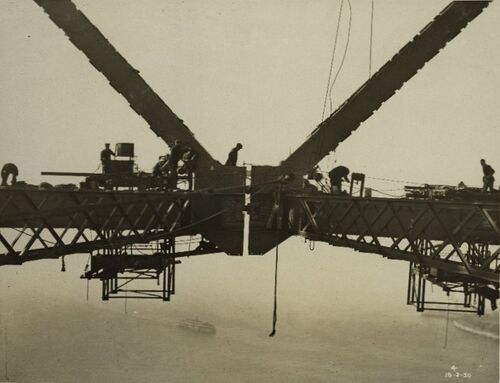
Bradfield’s and Freeman & Ennis’ papers give slightly different accounts of the final meeting of the half arches. Bradfield claims three fleets of cable lengthening of 3 inches, 4 inches and 5 inches, but Freeman and Ennis give a more complicated process. Three movements of 3 inches would not have been enough to close the arch, so the last 32 of the first cycle were released 4 inches, leaving them with a force of 104 tons and the first 96 with 109 tons. At the end of this first fleet the gap was approximately 2ft 6in with the northern half 3½ inches to the west and 2 inches higher than the south half.[7]
In the second cycle the first 32 were run out 3 inches, and the remaining 96 by 4 inches, resulting in a rage of forces in the cables of 113 tons, 108 tons and 103 tons.
According to Bradfield at the end of the second fleet the gap was 11 inches, the north half 4½ inches lower than the south half and still 3 inches to the west. This change from higher to lower by more than 6 inches would seem to be questionable and is not consistent with photographic evidence. On the morning of 19th August the third fleet commenced on the south side (sic), to bring that half down to the level of the north side and at 11am, when the gap was 4½ inches the locking bolts were forced home. The slacking of both sides proceeded rapidly during the day and at 5pm the gap was only ¼ inch.[8] The fall in temperature in the evening caused the gap to widen to ⅝ inch, but the slackening of the cables overcame the temperature effect at 10pm when the pins were first brought into direct contact, at a temperature of 62° F.
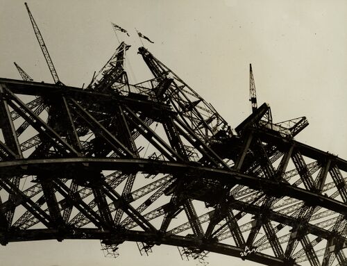
According to Freeman and Ennis, the third cycle let out each cable by a uniform 5 inches and it was toward the end of this cycle that the arches met about 4pm on 19 August 1930, though with the cooling of the evening they soon drew apart. With the junction assured the cable release was continued without the usual precautions and with movements of up to 6 inches.[9] By late evening cable release had overtaken cooling and permanent contact was made. As far as could be seen the two trusses met at the same time with no significant difference in level between the two, though the actual level was some inches lower than expected. In the lowering process the ends of the half arches had moved down by 4 feet 1¼ inches.
Although contact had been made there was minimal force across the joint. The cables, still stretched 21 inches, exerted a considerable force on the upper chord and in consequence of this tension the end post was still about 7 inches from its final calculated position.
Even after a further cycle of 7 inches on all cables they were left with three-quarters of their original tension and the pressure on the central hinge was only a quarter of the eventual total.
It was impracticable to detach any cable until the tension had been reduced to about half its original 108 tons. The slackening process was continued until all the cables had been slacked back about 14 inches and then it became possible to remove them. In six days, most of them had been removed, with only small tensions in those remaining.
To commemorate and celebrate the successful locking of the arch, consulting engineer and bridge designer Ralph Freeman gave to each Dorman Long employee an Australian florin, a two shilling coin. Some of these were made into keepsakes by their recipients.
In the meantime, the truss erection workers had completed the top triangles of the centre panels and the time had come to load the top chord.
- ↑ Bradfield in his paper states hand operated for the initial tensioning process, but a photograph exists captioned: Power Pump for hydraulic jacks at cable anchorage.
- ↑ Bradfield. The Sydney Harbour Bridge and Approaches. ICE 1934
- ↑ Born 1897
- ↑ Sydney Harbour Bridge. Manufacture of the Structural Steelwork and Erection of the Bridge.Freeman and Ennis ICE 1934
- ↑ Sydney Harbour Bridge. Manufacture of the Structural Steelwork and Erection of the Bridge.Freeman and Ennis ICE 1934
- ↑ Bradfield. The Sydney Harbour Bridge and Approaches. ICE 1934
- ↑ Bradfield
- ↑ The Dorman Long Book states that they were found to be in contact at this time
- ↑ This presumably means the use of higher jack pressures, with consequent risk of failure.


