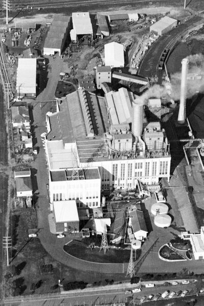
East Perth Power Station

From Engineering Heritage Australia

A documented history of the East Perth Power Station. Current proposal for a National Engineering Heritage Landmarker (EHNLM).


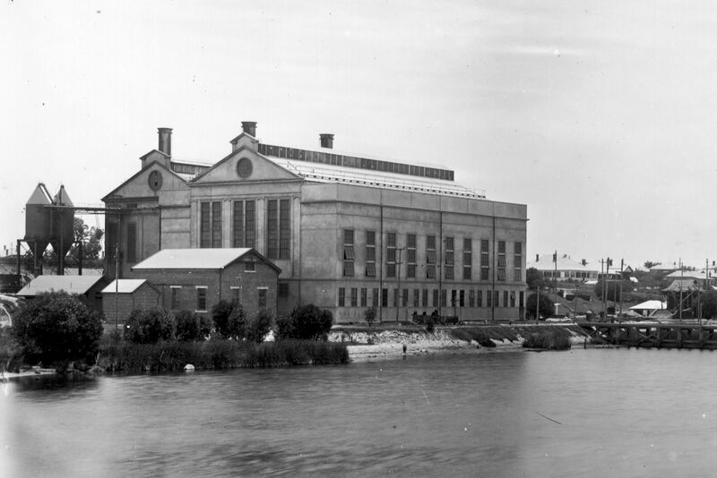
East Perth Power Station 1946
Source: SLWA b3473326_3
East Perth Power Station 2000
Source: John Archer: State Library

1. GENERAL

The East Perth Power Station was constructed between 1913 and 1916 by the WA government at a total cost of £538,000. It was the first State government operated public electricity utility in Australia, and largest power generating facility in the State until South Fremantle Power Station began operation in 1951. It operated for 65 years until decommissioning in 1981.

Originally a coal fired (for a short time oil fired) power station, it is one of the few remaining pre-world war one thermal power stations retaining its plant and equipment. The plant contains several generations of generators, spanning almost forty years, and is one of the most comprehensive in situ collections of steam turbine generating units in the country.

The power station originally operated on 40 Hz. To accommodate later power supply requirements, a frequency converter set unique in Australia and a rarity in a world context converted the original power station equipment output to 50 Hz.

The power station was important in the development of the State’s coal industry, based at Collie. Coal to fuel the power station was railed from Collie

Coal ash from the boilers was railed across the adjacent WAGR railway bridge and dumped on the site now occupied by the Optus Stadium. The ash trains were originally powered by an electric tramway and one of the electric locomotives is preserved at the Bassendean Railway Museum.

The station was decommissioned and closed in December 1981, as more advanced and cheaper methods of electricity generation made the facility redundant.

Further details on the history of East Perth Power Station can be found on East Perth's Engineering Industrial Heritage.


2. DESCRIPTION

The East Perth Power Station was the first electric power station in Western Australia which used steam turbines for motive power. Earlier power stations relied on less efficient reciprocating steam engines for their motive power.
At the time of its closure in 1981 the station comprised of the following operational items of major plant:

  • ‘B’ station: a single 25 Megawatt 40 cycles per second (Hz) turbo-alternator and associated boilers 11 to 14
  • ‘C’ station: a single 30 Megawatt 50 cycles per second turbo-alternator and associated boiler 15
  • Train loadout and coal storage area
  • Coal handling, crushing and pulverising plant and
  • a 40 Hz/50 Hz 25 Megawatt frequency converter.

The following ‘A’ station non-operational generator plant remained, each item in its original location within the turbine hall:

  • 4 MW turboalternator (Unit 3)
  • 7.5 MW turboalternator (Unit 4)
  • 12.5 MW turboalternator (Unit 5).
Unit No 4 A Station 7500kW Turboalternator
Source: John Archer: State Library
Unit No 7, C Station 30 MW 50cycle Turboalternator
Source: John Archer: State Library

---


3. EHWA NOMINATION to OWNER’S

The owner of the EPPS has always been under WA Government control. The ownership over the years has transitioned from the State tramways to the State Electricity commission. Since de-commissioning the State Government have it listed under Development of WA and with the interest of the City of Vincent.

Name of Item: East Perth Power Station

Description of Item: An early example of a fossil fuel power station employing turbo alternator technology
Engineering Heritage theme(s): Electric Power Generation
State/Territory Heritage listing: Western Australia
Type of heritage: Immovable|Tangible & Immovable|Intangible

Relevant Dates:

A new 7,500 K.W. turbine was put into operation at I the end of December, 1922,
‘A’ Station (Units 1-5): Construction started 1914; First unit in service 1916; Last unit (5) started service 1927; Last unit retired 1955.
‘B’ Station (Unit 6): Construction Started 1935/36, In service 1938; Retired 1981.
‘C’ Station (unit 7): Construction Started 1954, In service 1956; Retired 1981.
Location: Summers Street, East Perth
Coordinates (if known) 31°56'46"S, 115°52'49"E
Local Government Area: City of Vincent
Owner: DevelopmentWA
Marker Type sought: Engineering Heritage Marker
Figure 10. EPPS steel framework construction
Source: John Archer: State Library
EPPS_A_Station_Fully_Operational_1927.jpeg
Source: John Archer: State Library
Loading map...

4. HISTORICAL AND SOCIAL SIGNIFICANCE

(a) Importance in the course, or pattern, of the region’s history

There was an influx of hopeful people drawn to Western Australia during the gold rush of the 1890’s. For many, including a struggling writer named Henry Lawson, East Perth offered the best or only option when looking for accommodation in the burgeoning metropolis of Perth. This massive population boom was to steer East Perth along similar historical pathway’s to Sydney’s Balmain or Melbourne’s Collingwood.

In earlier colonial days, East Perth had been a prestigious residential location but by the early 1900’s, the concentration of industry and the establishment of a sewage plant at Claisebrook lessened its desirability and those who could afford to, shifted to the Western side of Perth.

In the period between 1913 and 1918 the Perth region was dependent on several unreliable electric power stations for power, tramways and lighting. Both the Perth city and the tramways power systems had been starved of investment for several years in anticipation of buyouts by either local or state governments. As a result, these systems failed to expand with population growth and the existing services were unreliable due to breakdowns and overloads. The tramways were the subject of the greater public unrest, largely due to erratic services, overcrowding and high fares.

In December of 1912, the Western Australian Government entered a verbal agreement with the City of Perth promising to build a new power station from which it would deliver electric power to the City for resale to all consumers within a 5 mile radius of the GPO.

Figure 9. Windan Bridge and New Foundations
Source: John Archer: State Library

East Perth was an ideal location for the power station. The selected site benefited from a nearby railway needed for its own rail siding and the Swan River which would provide the water needed for cooling.

Civil works commenced in 1914 and suffered innumerable delays due to the hostilities in Europe.


The first export of power was in 1916 and until the commissioning of a second power station in 1951, East Perth Power Station was the primary source of electric power for Fremantle, Midland and Perth covering an area bounded by the Indian Ocean, the Swan Valley, Mundaring Weir, Cardup and the Naval Base.

Over this period the Station occupied an important place in the commercial, industrial and social life of the population that it served. As well as its physical prominence on the banks of the Swan River, it was a steady source of informative and often controversial articles for the local newspapers.

The Station touched the lives of those who worked there, lived nearby or who visited to play, to fish or to swim near cooling water outlet which provided a steady supply of warm water all year long.

(b) Strong or special association with the life or works of a person, or group of persons, of importance in a region’s history

East Perth Power Station featured prominently in the lives of the Aboriginals and migrants who made East Perth their home principally due to this being an inner city location with affordable accommodation.


Communities:

East Perth was the preferred location for Aboriginals visiting or residing in Perth. Affordable accommodation, access to employment and education and the proximity to the Aboriginals Department offices and Royal Perth Hospital, both located in Wellington Street, made East Perth the city’s preferred gathering place.

For adult males, work at the power station shoveling coal was usually available. Two of the vital shoveling operations were keeping the chain bucket coal elevator free from fouling on spilled lumps of coal and emptying the railway wagons in which coal was delivered to the power station. In the years after World War II, the work force engaged in such menial labour was swelled by arrivals of migrants from Europe, in particular, the southern and eastern parts.

For the younger folk the power station provided a far more pleasant experience. Cooling water from the station’s condensers was piped into the Swan River where children could jump in and be carried downstream in a pleasant flow of warm water.

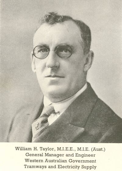
William Henry Taylor:

On a different tack, there is one name that dominates the developments of both the East Perth ‘A’ and ‘B’ power stations, William Henry Taylor.
From the time of his arrival in 1914 until his retirement in 1948, the name William Henry Taylor was synonymous with East Perth Power Station. Initially Merz & McLellan’s resident engineer, soon after his arrival, Taylor was employed by the Western Australian Government Railways and appointed to the role of Electrical Superintendent having responsibility for practically all aspects of the power station, the Tramways and their associated transmission networks. By 1920 his title was changed to General Manager Tramways and Electricity Supply.

Turbine Hall A and Reyrolle 20Kv Switchgear House
Source: John Archer: State Library
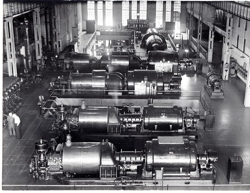
A Station Turbine Hall with Unit 1 - 4 Turbine alternators
Source: John Archer: State Library

From 1915 until 1946 he was the person responsible for all aspects of the day-to-day operations and all subsequent developments of the Power Station. If his manner seemed autocratic it was because he was a polymath whose abilities spanned all the technical disciplines required for the thermal generation of electric power. This extended beyond electrical engineering encompassing geology, chemistry, thermodynamics, structures and mechanics. His technical expertise did not detract from his business acumen demonstrated by his ability to run the undertaking despite the crippling commercial conditions under which it operated.

Given Western Australia’s extreme isolation from the national and international centers of engineering excellence, Taylor was the ideal candidate for this role.  

(c) Potential to yield information that will contribute to an understanding of the region’s history

The role of the Power Station in the state’s development is worthy of attention as is the impact it had on the locality.

Over the first 75 years of the 20th century, East Perth was a working class suburb mainly characterized by its indigenous and migrant communities. It would be fair to say that most residents of the suburb had some connection with the Power Station.

Many other industries operated in East Perth in this period that were vital to the industrial and economic development of the Perth region and beyond. The State’s isolation made the presence of these industries particularly critical. Some of the key industries in East Perth were:

1. Bunnings Brothers Timber yard
2. Millars Timber Trading yard
3. Tomlinson’s Engineering works
4. The Perth Electric Tramways Car Barn & Power House
5. The Claisebrook sewage collection tanks
6. The Western Australian Government Railways East Perth Locomotive Running Depot
7. The City of Perth Gas Works
8. The City of Perth Stables and Maintenance Depot
9. The Post Master General’s Workshops and Warehouses
10. Wunderlich’s Clay Tile works (later to become Brisbane & Wunderlich and to diversify into stainless-steel products, clay sewer-pipes, porcelain, refractory bricks, aluminium fabrication, building cladding and plastics.)
11. Stoneware Pottery Company’s Clay Pipe works
12. Hume Pipe Company’s Concrete Pipe works
13. Monier Patent Company’s Concrete works
14. The Australian Consolidated Industries Glass Bottle Factory
15. The Western Australian Government Mechanical & Plant Engineers yard
16. The Metropolitan Transport Trusts Bus Garages
17. Hunt’s biscuit factory
18. City Bottling Company
19. Faulding’s Pharmaceutical laboratories
20. Blue-Bell Ice Cream
21. Western Preserving Works.

  Other generic industries, many operating as small businesses, included: • Brickworks • Soap Making • Wire fencing • Dairies • Poultry Farms • Market Gardens • Confectionary makers • Bootmakers • Milliners • Dressmakers • Drapers & • Laundries.

The only industry that survived into the 21st century is the Claisebrook sewage collection tanks but these have been carefully concealed beneath park lands. The East Perth Power Station building stands as a monument to the suburb’s vibrant industrial past upon which much of the growth of Perth, and in turn the State of Western Australia, depended.

5. ENGINEERING AND TECHNICAL SIGNIFICANCE

(a) Creative and Technical Achievement
EPPS at Peak of development
Source: John Archer: State Library

The East Perth Power Station building was consisted of matching boiler house and turbine hall, producing a beautiful combination of form and function.

For economy and strength, the building is steel framed but for aesthetics it has a concrete facing applied over expanded metal mesh.

Cathedral-like in its size and its elegant geometry, the edifice presents magnificent views from the Swan River and the Windan Bridge (parallel to the alignment of the former Bunbury Railway Bridge).

The fine lines and symmetry which characterise its outward appearance serve as symbols to the method, order and logic that are the hallmarks of the machinery within.

Capturing the essence of the original designs is this extract from The West Australian, 11th December 1916, on page 8 entitled: ELECTRIC SUPPLY THE EAST PERTH POWER HOUSE COMMENCEMENT OF OPERATIONS.

“The power-house is a tall, graceful building, and is entirely constructed of steel and reinforced concrete; materials which give not only a high, and comparatively cheap structure and present an appearance of thorough finish, but which, it is claimed, render the building absolutely fireproof. The foundation consists of a concrete raft, reinforced and supported on piles, and the soundness of the construction is suggested by a total absence of vibration so frequently noticeable in such establishments, when the machinery is running.  

Traction Substation No 3 Canning Hgwy South Perth
Source: John Archer: State Library

On entering the premises, the visitor cannot but be struck by the mere handful of workmen who superintend the running of the big enterprise. A whole host of labour saving appliances, coupled with an economic system of control has reduced the number of employees required to a minimum, electrical control of the turbines, engine room telegraphs and telephones for transmitting orders to the boiler room, and numerous other devices of a similar type, all assisting to this end. Another special feature of the works is their arrangement upon the Independent Unit Principle, under which the plant is divided into three separate and distinct systems, each of which can be run entirely independently of the others. The type of system is one which has been developed by Messrs. Merz and McLellan…. By this means we are told, it will, despite any mishap at the station short of the total destruction of the works, be possible to maintain the supply of power as in normal times. With the introduction of the new source of power, the tramway system is being split into individual sections upon a somewhat similar principle, so that, in the event of trouble arising and the supply of power having to be cut off, the stoppage will be confined to one section only and will not cover the entire system, as under the old source of supply. Although the feeder systems have been divided previously to accommodate the new conditions, it was not possible to so operate with the old power house.

Turbine Room 1927
Source: SLWA b3473326_2

At first glance the works are reminiscent of the boiler room of a huge steamer, a network of steel ladders and gangways connecting their many ramifications. The chief departments of the station are the boiler house, the pump house, the turbine room, and the switch house. The coal which is used to feed the boilers-and it may be mentioned that it is a Collie coal-is brought from the railway into a special siding, having hoppers over which the trucks are placed and their contents dropped into the conveyor-filler. It is then weighed over an automatic weighing machine, and the weight having been recorded on a dial it is elevated to the boiler room coal hoppers at the top of the building, where there are bunkers of a capacity of 300 tonnes. The coal is then fed by chutes to the chain grate stokers, and after it has been burned the ashes are dumped into ash containers or hoppers underneath the boilers in the basement. By means of a suction ash plant it is then discharged into two large conical ash containers at the east end of the building, whence the ashes are dropped through hopper spouts into trucks and removed. From the time the coal is emptied into the elevator hopper to the time it is transformed into ashes it is Not Touched or Handled Manually in any way; under normal conditions some 40 tonnes per hour can be handled.”

The complete newspaper article forms APPENDIX A which is followed by a supplementary newspaper article forming APPENDIX B.  


(b) Demonstrating the principal characteristics of an aspect of the development of engineering practice

5.1 Independent Unit principle

The Independent Unit Principle, invented by Charles Merz, divides generating plant into distinct and separate systems, each of which can be run entirely independently of the others. Thus, a failure in one generating unit is confined to that system leaving the remaining units unaffected. This improves the overall reliability of the power station. This principle has been standard design practice for thermal power stations throughout the 20th century and into the 21st century.

Commissioned in 1904, the Carville "A" power station belonging to the Newcastle-upon-Tyne Electric Supply Co, was the world’s first power station built on this principle.

WA270 Reyrolle 22kv SwitchGear
Source: John Archer: State Library


Another aspect to the Independent Unit principle was applied to the design of the following power distribution networks: • The power station 20,000 V and 6,000 V (AC) high voltage networks, • The tramways 600 V (DC) networks and • The City Council’s 440 V (AC) networks (which were also designed by Merz.)

Each network consisted of several feeders, each feeder being electrically isolated from its neighbouring feeders. Thus, a fault on feeder ‘A’ would be automatically detected and its associated circuit breaker tripped leaving feeders, say ‘B’ and ‘C’ intact continuing to provide uninterrupted service. Furthermore, by the strategic placement of ‘normally open points’ between adjacent feeders, one feeder could support all or part of a neighbouring feeder’s load during planned or unplanned outages.

In order to maximise physical reach, and grow revenue, feeders supplied a single mesh of copper wires. In common parlance, it would be said that all feeders operated in parallel with each other.

This meant a fault on a line in any part of the network affected the entire network, typically causing complete blackouts until the fault could be located and then isolated for repairs. Depending on the system concerned, a single fault would interrupt supply to either all of City Council’s customers or to all of the tramcars.

5.2 Synchronisation

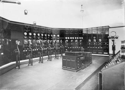
Control Room 1927
Source: SLWA b3473326_1

Running up an AC generator to run in parallel with a running power system requires that phase and frequency be running in synchronism prior to connecting the incoming machine. This operation is referred to as synchronisation and it is arguably the most important control function in any AC power station regardless of age or size. A mistake is quite likely to result in major damage or total loss of a complete generating unit. In the earliest of AC power stations, synchronism was indicated by the cranks of engines being in the same rotational position. This was best achieved by using markers and the stroboscopic effects of the station's lighting or by using a voltage transformer and a lamp. A less effective alternative method was to remove the caps to the valves of the engines’ HP cylinders and adjust the running so that the release of steam at each cycle coincided. None of these methods was applicable to turboalternators.

The invention of the synchroscope eliminated these crude methods by providing simple ‘raise’ or ‘lower’ engine speed commands on the large dial of an analogue measuring instrument.

East Perth’s turbine Hall was equipped with a pair of ornate synchroscopes suspended overhead in front of the row of high voltage switch panels. With one due north and one due south of the power station controller’s desk, operators had a clear view of the instrument no matter which generator circuit breaker panel they were preparing to switch.

The principle of operation they used has not changed in over a century of power station operations.

Although East Perth was not the first Western Australian power station fitted with synchroscopes, it does provide an example of the prominent positions these instruments commanded in early AC power stations.

5.3 Merz Price Differential Protection

Developed in 1904, this protection was applied to all of the alternators installed at the power station. Up to present times, it remains one of the most common types of protection applied to both synchronous machines (e.g. turboalternators) and substation busbars. Together with low impedance differential protection and distance protection, this type of protection was pivotal to the protection of large interconnected networks.

The major benefits of this type of protection are: • Its speed of operation and • Its ability to protect precisely defined zones while being immune to faults outside of the protected zone. This form of protection, more commonly referred to as ‘high impedance circulating current differential protection’ has endured, and despite competition from comparable low impedance differential systems remains the preference in many applications because of its relative simplicity.

5.4 Condenser Technology

Unit 4 Steam Ejectors
Source: John Archer Western Australian Library

The first three turboalternators in ‘A’ station relied on costly multi-stage air pumps to draw and maintain the condenser vacuum needed for normal turbine operation. Because the air pumps were powered by electric motors, when starting a turbine without auxiliary power the exhaust steam from the turbine had to be vented to atmosphere. An electrically operated valve was provided for this purpose. Without electricity to operate the valve control motor, the valve needed to be manually operated incurring an extra 20 minute delay in the starting sequence. Turboalternators 4 and 5 were supplied with steam jet ejectors which relied on the Venturi effect to draw the condenser vacuum. These required no auxiliary electrical supply for operation making for much faster black starting times. Steam ejectors replaced air pumps over a 40 to 50 year period in the cycle of steam power station development and formed part of the condensate feed heating circuit to minimise steam (treated water) losses and recover valuable heat. In more recent times, however, air pumps were reintroduced into the condensing system for two advantages that they offered: • The cost of electric motors and air pumps reduced relative to steam ejectors & • In conjunction with steam ejectors, a relatively inefficient set of steam ejectors could be used to rapidly pull vacuum (with or without auxiliary supplies) and a modestly rated air pump could be used to maintain the vacuum during normal running times.


(c) Uncommon or rare aspects of the development of engineering practice

6.1 Power Station Control

Reyrolle 22KV OCB Remote Control Panel
Source: John Archer: State Library

The early images of the turbine hall show its similarity to the bridge of an ocean liner. The power station controller’s desk was squeezed between the No 2 alternator (non-drive end) and the long row of switch panels that lined the eastern wall of the turbine hall. Rather than looking out at the sea and the horizon, the operators of the power station watched the expertly crafted instruments mounted on the 2 inch thick polished slate that formed the operating panels of the high voltage switchgear cells. There was one mechanical ‘ship’s telegraph’ link between the controller’s desk area and each pair of boilers. These allowed operators to communicate steam requirements to the boiler crew and allowed feedback from the boiler crew. Unlike a ship’ telegraph, there would not have been any need of ‘reverse’ segments!

The power station operators could also communicate by telephone with attendants located at the condensers beneath the turbine house floor. In 1928, as part of the extensions made to accommodate the new No. 5 12.5 MW turboalternator, a more advanced control room was built in an annex on the eastern side of the building. This was the first of several dedicated control rooms at East Perth which eventually encompassed visibility and control of an entire interconnected power system.

6.2 Merz Hunter cable ring main protection

In addition to overload protection, the 6,000 V feeder cables supplying the city ring main cable system were protected by the Merz Hunter split conductor protection system. This type of protection was invented by P. V. Hunter in 1911. Three phase high voltage distribution systems typically employ three core cables where each phase is associated with one core. In the 6,000 V feeder cables there were two cores for each phase resulting in a cable with six cores. In the basement level of the power station a current transformer was fitted over each of the six cores. (a CT is a transformer that linearly transforms large current into small current that can safely be passed through meters and protection relays.) That is, there was one pair of CTs per phase. Across these pairs of CTs was a current measuring relay sensitive to any inequalities in the CT outputs. During normal conditions the CT outputs were equal and there was no ‘spill’ current. If a cable fault occurred, there was a very high probability of a substantially difference between the CT outputs whereby the ‘spill’ current would operate the relay. In turn, the relay would trip the feeder circuit breaker (‘oil switch’) thereby isolating the faulted cable from the remainder of the power system. Unlike Merz Price which persists throughout the industry up to the time of writing, Merz Hunter protection proved unsuccessful. Its basic premise of operation was that on any one of the three phases supplying power, the current would be shared equally by that phase’s two conductors. In practice, this was not the case and unbalance from any unusually large currents caused nuisance tripping and unnecessary disconnection of customers.  

6.3 Common Steam Header

4MW Turboalternator Condenser
Source: John Archer: State Library

The ‘A’ station employed a common steam header which collected the steam from all boilers from where it could be fed to any of the steam turbines.

This approach greatly enhanced the flexibility of boiler operations but was costly requiring additional piping and many isolation valves. These increased capital costs, maintenance and heat losses particularly in large power stations where steam is piped over long distances. With the improved reliability of boiler plant and the growing size of power stations, the benefits of steam headers diminished until they were eliminated.

6.4 Peak Load Predictions

Control Room 1927
Source: SLWA b3473326_1

One of the most important activities in the operation of any public electricity supply is load prediction. Electrical load, referred to as demand, needs to be accurately predicted so that sufficient generating plant may be scheduled to meet the demand. Of particular importance is peak demand, which not only dictates the day to day power station operations, but mid term maintenance plans and long term investment plans.

For a large part of the power station’s lifetime peak load always occurred on Tuesdays. This stemmed from how was society regimented: Monday was washing day, most likely manually done, and Tuesday was ironing day. Any household with the means would be running an electric iron, one of the most sort after conveniences provided by electricity.

Such was the delicate balance between supply and demand in the early 20th century that when the electric arc furnace at the Vicker’s foundry in Bassendean. engineering works was about to start, a phone call to the power station was required to ensure that sufficient generation was available to take up the sudden increase in demand.

6.5 Coal Handling

Telpher Ferrying Coal on south side of Wellington St, to EPPS on the North side

At the start of its operational life the expectation was that coal handling would be entirely mechanized without the need for any manual handling. As events unfolded, this was proved not to be so. Up to 30 June 1946 the power station operated under the control of the WAGR which provided bottom dump rail wagons for transporting coal to the power station siding. It seems that with formation of the State Electricity Commission these wagons were recalled for WAGR use. Thereafter, coal was delivered in general purpose wagons which were fitted with side opening gates. A certain amount of coal would empty under gravity but what remained needed to be shoveled out. For this job a team of typically five, but as many as seven, men, were assembled with four shoveling while the other(s) rested. This mode of operation persisted until the commissioning of the station’s wagon tippler in 1955.

In 1924 a new chain bucket coal elevator was installed to accommodate new coal storage arrangements. The horizontal tray conveyor used for distributing coal to the bunkers inside the boiler house was also duplicated. The elevators raised coal from a basement called the ‘filler pit’. Keeping the buckets full of coal and preventing fouling on spilled coal necessitated long hours of shoveling coal in the near total darkness surrounded created by clouds of coal dust. In the event of overloading or stalling, a shear pin would fail allowing the contents of the buckets to plummet downwards into the pit. On such occurrences, momentous effort was required to remove debris and restore the elevator to service before the bunkers inside the boiler house were emptied. It is noted that the ‘A’ station coal elevators also fed the ‘B’ Station boilers. Manual intervention was also required inside the ‘A’ station boiler house. Above each boiler was a coal bunker capable of storing up to 40 tons of coal which was fed through a chute onto a chain grate or retort stoker for combustion inside the boiler. A bunker attendant was employed to monitor the level of coal in each bunker. Sometimes coal adhering to the sides of a bunker interrupted the flow to the boilers and one practice was to jump into the bunker to loosen the stuck coal. In 1929, day labourer Harold Scott was working alone as a bunker attendant on night shift. It was only during the next shift that a blockage was reported in the No 7 bunker. On investigation, Harold’s body was found there, suffocated under 35 ton of coal. Thereafter, management instituted a policy whereby a minimum of two workers had to be in attendance if anyone planned to enter a coal bunker.


(d) Yielding new or further substantial scientific and/or archaeological information; and/or is an important benchmark or reference site or type

East Perth Power Station contains examples of early thermal powered turboalternator generating equipment.

The document ‘East Perth Power Station Machinery Inventory’ prepared for the Metropolitan Redevelopment Authority in October 2019 provides recommendations for the management of each major plant item and its associated equipment in the context of future change or adaptive re-use of the power station. Retention of all the remaining plant and equipment in the East Perth Power Station would be a desirable outcome, as each item was once integral for the electricity generation process. The document, however, acknowledges that some plant items and associated components are in a very poor condition.

Furthermore, at the time of writing, there is no intention of fully restoring or using the plant and equipment for its original function. The retention of selected machinery that either demonstrates the cultural heritage value of the EPPS or provides tangible evidence of its former function as the power house of Perth was recommended.

The document identified “The ability of the remaining plant and components to symbolise or represent the overall operating system in which it functioned” as a key determinant of the future management plan.

is taken from the machinery Inventory prepared for the Metropolitan Redevelopment Authority in October 2019 which identifies examples of significant objects remaining on the site (as well as some that have been removed or demolished.) It includes site plans identifying the locations of the listed items.

7. SUMMARY STATEMENT OF SIGNIFICANCE

East Perth Power Station needs to be recognised for the significant contributions it has made to the State of Western Australia and to the people who have lived near it or relied on it for their livelihood. Its history reflects the important milestones that have defined Western Australia’s development in good times and bad times. The plant and machinery remaining at the site are examples of some of the key components that constitute an early fossil fuel steam power station. With appropriate interpretation, the site can afford future generations with the understanding of how the burning of fossil fuels, the raising of steam and the conversion to electricity was achieved. Furthermore, the potential exists to exhibit the changing forms and theories of operation as each of the technologies developed over the life of the station.


8. HISTORY

8.1 THE ORIGINS OF THE POWER STATION

In late l912 there was a diversity of power stations in the Midland/Perth/Fremantle area with most stations operating independently and producing different types of current at different voltages. Some were owned by local government, some by state government and others by private industries. Only local government generated power for sale as a commercial activity. The other two types of owners generated for their own consumption only.

Figure 1. Fremantle Municipal Power House
Source: John Archer: State Library
FIgure 2. Fremantle Municipal Tramways Power House
Source: John Archer: State Library


The most advanced power station of the day, illustrated in Figure 1, Figure 2 & Figure 3, belonged to the Fremantle Municipal Tramways and Electric Lighting Board. As well as generating direct current for tramways and sewage pumping, alternating current was generated for lighting and power. What made it superior to the other stations of the Perth area was the manner in which the alternating current was distributed. A high voltage distribution system was employed capable of transferring power over relatively great distances. Initially 3,300 V, the network was later upgraded to 6,600 V system. These high voltages were stepped down to 220 V to supply consumers with a two-phase alternating current supply. The frequency of the supply was 50Hertz (1 Hertz = 1 cycle per second), the same frequency as that generated at the Western Australian Government Railways (WAGR) Midland Junction Ways and Works power station shown in Figure 5. For information, Figure 6 & Figure 7 are listings of the electrical equipment from the power station that were offered for sale after its closure.

Figure 3. Fremantle Tramways Power House Boiler
Source: John Archer: State Library

Midland Junction, Claremont, Subiaco and Perth City Councils each operated their own direct current plants. Of these, the Perth City Council operated three power stations including the largest and the oldest in the region. A novelty at the time, was the use of a telpher to supply coal to the Council’s oldest power station in Wellington Street. This means of conveyancing is exhibited in Figure 8. The Perth City Council was not involved in the electric power business until 14th February 1912 when it acquired all the electric works (and the gas works) of the Perth Gas Company. The largest of its newly acquired power stations was on land due to be resumed by the WA Government. The imminent loss of this major station forced the Council to plan for the future of its entire electricity supply network. For advice, they engaged the services of Mr Forbes-McKay, Chief Electrical Engineer for the Sydney City Council. Forbes-McKay recommended replacing the existing direct current system, along with all three of its power stations, with a single new power station producing alternating current and employing high voltage distribution. The Council favoured this proposal and selected a site on which such a station could be built. As events unfolded, they would never need to build this power station.

The tramways in Perth City and surrounding suburbs were owned and operated by a private firm, the Perth Electric Tramways (PET) Company. This Company's power station in Kensington Street, East Perth supplied 600 volt direct current exclusively for powering the tram cars. One of this power station’s main generators is shown in Figure 4. The Western Australian Government was due to take over all assets of the Perth Electric Tramways Company on 1 July 2013. It was decided that the Western Australian Government Railways (WAGR) would have responsibility for running all aspects of the tramways. The new Premier of Western Australia, also the Minister for Railways, John Scaddan, requested the outgoing manager of the PET, Mr H Somerset, to report on improvements to the system which was operating well beyond its capacity. Mr Somerset's report of 30 September 1912 recommended a complete re-modelling of the power station and the adoption of high voltage, alternating current distribution to supply the outlying areas. The WAGR was not sufficiently experienced to make a decision on Somerset’s proposals so the Commissioner of Railways prevailed upon the WA Government to seek advice from Charles Merz, a world renowned expert in all matters to do with electrical power, who was in Melbourne at that time. Although the brief was to investigate the upgrading of the tramways, when addressing the need for a new power station Merz’s report gave two alternatives: one was to build a station of three turboalternator sets, each of two megawatts, which would be adequate for the tramways only; the other was for a station of three sets, each of four megawatts, which could supply tramways as well as light and power supply for the metropolitan area. He recommended either station should generate alternating current at fifty Hertz and employ high voltage distribution. After a whirlwind round of meetings between 21 and 30 December 1912, a power supply agreement was reached in principal between the Government and the Council. The Council would buy from the Government the current for sale to its consumers and have no need to establish its own power station. Thus, Merz’s second option was to be adopted. It was thought at time that the Government would receive additional revenue from the sale of current to the Council to help finance the power station.

8.2 INITIAL CONSTRUCTION

Figure 12. Southern End Power Station
source: John Archer State Library

For reasons that have never been made clear, when the specifications for the station were written, forty Hertz, not fifty Hertz, plant was stipulated. More discussion of this surprising action is provided under the ‘Frequency Changer’ heading on Tenders were invited and several were returned before the end of February 1913. The power station building was to be completed and the boilers steaming by 1st January 1914. The turbo-alternators were to be commissioned within ten months of the placing of the order. None of these targets were met, mainly due to the eruption of war in Europe. The successful tenderers were:- Babcock and Wilcox for the power station building, boilers, pipework and overhead crane. Willans and Robinson for the turbo-alternators, condensers, air pumps, circulation water pumps and air exhausters . Allegemeine Electricitats Gesellschaft (A.E.G.) for the switchgear, transformers and motors. Callenders Cable and! Construction Company for the supply and jointing of cables.

750kW Rotary Converters

British Westinghouse Electric and Manufacturing Company for the four 750 kilowatt rotary converters. With the onset of the 1914-1918 war the order with A.E.G. was automatically cancelled. Tenders were recalled with the successful tenderer being British Westinghouse. Work on the site for the new power station commenced in September of 1913 under the direction of the Chief Engineer, Existing Lines of the Western Australian Government Railways. By April of 1914, in excess of 1300 jarrah piles had been driven as shown in Figure 9. After being cropped to their correct heights the piles were capped by a large concrete raft which would support the whole of the power station. In May of 1914 erection of the steel frame of the power station building, shown in Figure 10, commenced under the supervision of William Henry Taylor. Taylor was the former Deputy Electrical and Tramways Engineer to the Walthamstow Council in England. For economy, a steel frame was selected for the power station building. To improve aesthetics, external panel walls were made by coating large sheets of expanded metal mesh with a veneer of concrete. Figure 11 & Figure 12 are images captured during the construction. The initial installation consisted of a boiler house suitable for eight boilers but with only six installed, a pump house for four pumps with three installed, an engine room for four turbo-alternator sets with three installed and an extendable switch house with more than one dozen 6,000 volt oil switches installed. Figure 13 shows the turbine hall with its three initial generating sets. The original boilers were numbered 1,2,3,4,5 and 7. Each was rated to raise steam to a temperature of 600 degrees Fahrenheit and a pressure of 200 pounds per square inch at a rate of 20,000 pounds per hour.

The steam turbines, each rated at 4000 kilowatts, were built by Willans and Robinson of Rugby, England. Prints of the engineering drawings of these turbines show they were manufactured to metric dimensions modified to accept imperial standard fasteners. Steam expansion in each took place in a single cylinder. The first two rows of moving blades were of the impulse type forming what is called the Curtis wheel. The remaining blades were all reaction type. Speed control of the steam turbines was effected automatically by open governors.

Willans and Robinson Unit No1 4MW Turbine

These turbines could run at reduced output by venting exhausted steam directly to the atmosphere. This would automatically take place whenever vacuum in the condenser was lost. It was necessary to employ the same mode of operation when re-starting the station after a loss of electricity supply because the Edwards air pump derived its motive power from an alternating current electric motor. The role of this air pump was to evacuate the condenser and without a vacuum it was necessary to vent steam directly to the atmosphere. To allow this operation to take place the turbine main exhaust valve had to be closed and without electric power manual closing took up to twenty minutes to complete. This feature of operation was a considerable hindrance to power station staff endeavouring to effect 'black' starts with minimal delay.

'Black' starts were usually made with the generator main switch closed and all of the generator auxiliary motors connected. In this way, as the turbo-alternator developed speed so too did the necessary pumps. Thus, when a unit reached operating speed, its condenser would be cooled and evacuated and full power delivered by the unit.

The alternators were built by Brown Boveri of Switzerland. They each had a continuous rating of 4412 kilovolt-amperes (kVA) and a half hour rating of 5300 kVA. These ratings were adequate for 3,000 kW continuous output and 4,000 kW intermittent output. Figure 14 shows the nameplate of the Brown Boveri unit 3 alternator.

Brown Boveri Unit 3 Alternator Nameplate
source: John Archer State Library

The 6,000 V switch house was built in a fashion that became obsolete not long after its construction. Integral with the turbine hall, it consisted of a four floored structure on the eastern side of the building. The switch house was divided into vertical cells, hence the equipment occupying it was known as 'cellular switchgear'. Each cell contained one electrical circuit spread over four levels. Circuits could be either incomers or feeders. Each circuit was connected by one or more cables which terminated on the lowest or basement level. On this level each cell contained a switch for isolating the switchgear from the external circuit, an earth switch for safety as well as instrument transformers for sensing current and, in some cases, voltage. The level above contained the British Westinghouse 'H' oil switches (commonly referred to as circuit breakers). These switches were available at ratings of 300, 600 and 1500 Ampere. They were manually operated but could be automatically tripped in the event of overloads or short circuits. On the next level up were the selector switches which enabled a circuit to be connected to either the front busbar or the rear busbar. The top level housed the duplicate power station busbars.

Figure 15 depicts an example of a 6,000 volt oil switch. The one exhibited was installed at the No 5 substation in Palmerston Street, and is similar to those supplied for the power station. Equipment for the protection, control and metering of each circuit was fixed onto a two inch thick (50mm) polished slate panel. Circuits feeding remote substations were protected by Merz-Hunter split conductor protection. The generators were protected by Merz-Price differential protection.

There was no control room in the initial installation. The controller sat at a desk in front of the generator control panels, giving him control of the main circuit breaker and field current rheostat of each set. He could communicate with the engine drivers and the boiler house either by telephone or ship's telegraph.

8.3 ‘A’ STATION

With the exception of the 20 kV switchgear, the first phase of the 'A' Station development occurred between 1913 and 1917. Turboalternator 4 and the 20 kV switchgear were completed in 1922 and turboalternator 5 in 1928.

Generator 1951
Source: SLWA 234,989PD

The first commercial generation took place on 3rd December 1916. One customer, however, the Peerless Flour Mills at West Guildford, required supply in advance of this date. The challenge was met in a novel way. The source of the electrical energy was the old Tramways power station in nearby Kensington Street. The 600 volt direct current supply was brought from the trolley wire into the new power station and applied to the rotary converters to make them run inverted. That means to convert direct current to alternating rather than vice-versa. The alternating current produced was stepped up to 6,000 volts by the rotary converter transformers, which in normal service were step down transformers. The 6000 volts was applied directly onto one of the Midland Junction overhead lines. The Midland Junction lines were intended to supply the railway workshops and various customers along the route at 20,000 volts. With the line operating only at 6,000 volts, a 6000/440 volt step down transformer would be needed. For this purpose, a unit transformer was borrowed from one of the turbo-alternator sets being assembled at the power station. Hence the first electrical supply from the East Perth Power Station was generated from elsewhere.

Figure 11. A Station Boiler Construction
Source: John Archer State Library

Coal consumption of 'A' station was in the order of four pounds of Collie coal for each kilowatt-hour of electricity produced. The older stations it replaced used approximately thirteen pounds of the same type of coal for the same output. This improvement in efficiency resulted from improved coal burning techniques; the use of turbines which could convert energy more efficiently than reciprocating engines; and from raising the steam to greater temperatures and pressures, which enabled a greater percentage of its stored energy to be converted to useful work.

The first extensions to 'A' Station were completed in 1922. Turbo-alternator number 4 a 7,500 kilowatt Parsons set, had two advantages over its the three predecessors: a fully enclosed oil relay governor and steam ejectors shown in Figure 16. The oil relay governor improved speed control and the steam ejectors enabled the condenser vacuum to be maintained in the absence of electricity supplies.

With the new turbo-alternator came two new boilers, numbers 6 and 8. They were by the same maker and of the same rating as the original boilers. They were, however, fitted with Sanford Riley multiple retort stokers in place of the older chain grate stokers. These gave superior coal combustion, as well as allowing the burning of coal that previously would be rejected.

Also in 1922, the original 20,000 V switchgear contract with was completed by Metropolitan Vickers, the company which took over British Westinghouse. At the time, their high voltage switchgear was considered superior to all others in the electrical world. Rather than requiring a brick structure four stories in height, a single switch was less than 8 feet high with a width of not more than 4 feet. These dimensions permitted the installation of a suite of 8 switches in an inconspicuous fibre-cement shed, named the ‘Reyrolle Switch house’, located opposite the 6,000/22,000 V step up transformer compound. Ultimately, 11 oil switches were installed there. When the switch house was made redundant, the switches were relocated for service at Hadfields substation in Bassendean. They served the local 22 kV network up to the 1980’s when they were consumed in a fire started during cable jointing. Anecdotal evidence was that a gas torch being used to liquify the pitch within the cable box of one of the switches had been left unattended and the molten pitch had ignited.

For the previous six years each step up transformer had been directly connected to one of the four 20,000 V transmission lines used for supplying Midland and Fremantle. The new switchgear afforded greater reliability and flexibility whereby any transmission line or any step up transformer could be connected to one of two 20,000 V busbars.

In 1924 Western Australia's first electric train went into service. A Metropolitan Vickers electric locomotive was commissioned to fetch coal from the adjoining railway yards and take away ash-filled rail wagons. It replaced steam locomotives which attracted costly demurrage charges. Power for the new locomotive was derived from the 600 volt Tramways switchboard. It remained in service until 1969. After retirement, it was taken for display at the Australian Railways Historical Society's Museum, at Bassendean, Western Australia.

Another advancement in 1924 was the completion of a new coal elevator, rail siding and coal bins. Prior to this installation there was a single coal handling system relying on one bucket conveyor inside the boiler house. Breakdowns, which were frequent, meant excessive manual handling of the coal.

In 1925 work commenced on a second scheme to increase power station capacity. The expansion was completed in 1928 with the commissioning of new turbo-alternator number 5, a 12,500 kilowatt Parson's set. Within this turbine steam was expanded in two stages, that is in a high pressure and a low pressure cylinder. The existing turbines had only one expansion stage each. Two new Babcock and Wilcox boilers, numbers 9 and 10, evaporated water at the standard rate of 65,000 pounds per hour and a maximum rate of 100,000 pounds per hour. This far exceeded the 20,000 pounds per hour in each of the earlier boilers. The stokers of the new boiler were Riley multiple retort forced draft type, similar to those used on 3 of the 8 smaller boilers. Also commissioned were: new switchboards for the low voltage auxiliaries; a 500 kilowatt Metropolitan Vickers geared turbo-alternator known as the 'house set' intended for 'black starts'; a new control room; new offices; and extensions to the 20,000 volt switchgear.

When complete, the ‘A' station consisted of five turbo-alternators all on a common steam range. The steam conditions were specified at 600 degrees Fahrenheit at a pressure of 200 pounds per square inch. Power output averaged 1 kilowatt hour for 3 pounds of coal.

When ‘B’ Station’s TA No. 6 returned to service in l952 there was little use for 'A’ station, other than during times of peak load, breakdowns or black starts.

By the end of 1955 'A' station had retired.

Further details from the time of ‘A’ station’s opening are provided in APPENDIX A. Details of the lines and substations associated with the power station from the same time period may be found in APPENDIX B.

8.4 ‘B’ STATION

EPPS 1939 with installation of 3 of B Station Boilers
Source: John Archer: State Library

The 'B' station consisted of three boilers and one turbo-alternator, installed between 1935 and 1938, plus an additional boiler commissioned in 1955. It was built onto the northern end of 'A' station. The thermal efficiency of 'B' station was nearly 3 times that of 'A' station. This improvement was mainly achieved by burning pulverized coal, which enabled steam to be raised to a temperature of 815 degrees Fahrenheit and a pressure of 625 pounds per square inch.

Unit No 6, B Station 25MW 40 cycle Turboalternator
Source: John Archer: State Library

C A Parsons supplied the 25,000 kilowatt, number 6, turbo-alternator. It was the last forty Hertz set to be installed at East Perth. The 'B' station boilers, supplied by International Combustion Limited, were each rated to evaporate 125,000 pounds of water per hour. Boilers 11, 12 and 13 were commissioned initially with Boiler 14 entering service in 1955.

Pulverized coal was produced by two Lopulco coal mills per boiler. Each mill could reduce eight tons of lump coal per hour. Each boiler was fitted with a Lodge Cottrell electrostatic precipitator to clean the flue gases of fly ash. The single chimney, which served all four boilers, required external reinforcing after developing a bow in its side soon after starting service.

Disposal of ash from the 'B' stations boilers and precipitators was effected by a water sluice system. Ash hoppers emptied into channels of running water and the slurry that formed was pumped away from the power station. Some slurry was used to reclaim land on the power station side of the Swan River. Most, however, was pumped over the river to Burswood Island. At the same time, the ‘A’ station’s ash disposal system was converted from a dry ash handling system that had reached its technical limitations to the new wet system. The older ‘A’ station system required the manual emptying of rail wagons laden with dry ash and incurred high labour costs.

In 1955 the fitting of oil burners to the 'B' station boilers allowed firing on either coal or oil.

The 'A' station steam range could be supplied from 'B' station by means of pressure and temperature reducing valves. In this way, the new boilers were able to power the old turbo-alternators. Such an arrangement increased the 'A' station boilers availability for maintenance. Because of its high thermal efficiency, 'B' station became the main source of electrical energy for the Perth area between 1939 and 1951.

Further details are provided in APPENDIX D The ‘B’ Station of the WA Government Electricity Supply East Perth Power Station by W. H. Taylor.  

8.5 THE FREQUENCY CHANGER

40 to 50 cycle Frequency Changer
Source: John Archer: State Library

During the initial construction of the East Perth Power Station there was open argument in the Press over the choice of alternating current frequency. The choice of a 40 Hertz power station required the replacement or modification of all of the 50 Hertz alternating current motors at the Midland workshops and throughout the Fremantle area.

A possible explanation for this stance rests with the attitude of Premier Jack Scaddan. Scaddan had personally negotiated the commercial aspects of the electricity supply agreement between the West Australian Government and the Perth City Council. The agreement was totally uneven in terms of cost recovery from the Council and the restrictions on the Government’s ability to compete for the majority of the region’s customers. To compound matters, the contract had a term of 50 years during which time, the supply of current to the Council was capped at 0.75 pence per kilowatt hour. The Council had been in negotiations to purchase the Perth Gas Company since 1906 and by the time of the agreement with Scaddan had been operating power stations for nearly two years.

With seemingly nothing to ameliorate the Government’s position, it is possible that Scaddan took the only potential advantage that the Government could have over the Council. It was accepted knowledge in the industry that lower frequency power was most efficient for electric traction. For general power and lighting, 50 hertz was still the favoured frequency because light flicker was considerably more perceptible at lower frequencies with 40 Hz considered the lowest acceptable frequency.

During his tour of the northern hemisphere in early 1913, Scaddan experienced a journey on the Simplon railway, famed for its technological marvels. This railway operated on a power supply frequency of 16 ⅔ Hertz.

Frequency Converter Set 1951
Source: SLWA 235,005PD

40 Hertz might have been selected in anticipation of the AC electric traction applications under consideration at the time. The Council’s power and light customers would, on the other hand, be on the limit of experiencing lamp flicker. As it eventuated, the Government’s plans for AC electric traction laid dormant until 1988. The labour government under Peter Dowding ordered 43 two-car electric rail units from Walkers Limited of Maryborough in Queensland. This was the start of the electrification of Perth's suburban rail network. A new rail line electrified at 25,000 V and mostly located within the Mitchell freeway easement, was built from Perth Station to Whitfords Station 21 km north of Perth. It commenced operation in 1991, 78 years after the decision to adopt 40 Hertz was made. Ironically, it operated at 50 Hertz, not 40.

As the electric power supply industry grew, 40 Hertz systems became a rarity among supply authorities such as the Western Australian Government Electricity Supply.

In 1944, the Western Australian Government appointed Mr V. J. F. Brain, Chief Electrical Engineer of the NSW Public Works Department, to investigate changing the system frequency from 40 to 50 Hertz. He was in favour of 50 Hz and estimated cost of conversion from 40 Hz to 50 Hz as £660,000. After receiving a pledge of £300,000 in assistance from the Commonwealth Government, the Western Australian Government opted for 50 Hz. Subsequently, a fifty Hertz station was ordered for construction at South Fremantle.

The new turbo-alternators for South Fremantle were to be supplied by Metropolitan Vickers who were also contracted to supply a frequency changer for East Perth. The frequency changer had three tasks:- 1) to convert 50 Hertz current to 40 Hertz, 2) to convert 40 Hertz current to 50 Hertz, and 3) to correct power factor, effecting improved utilization of plant.

The frequency changer consisted essentially of two large synchronous machines, each capable of transferring 31,250 kVA corresponding to twenty-five megawatts at a power factor of 0.8. During the frequency changing operation, one machine would act as a motor and the other as generator. On the same shaft was a fifty Hertz induction motor and a forty Hertz induction motor. One or the other could be used to run the frequency changer up to speed, depending on the most readily available frequency of supply. To avoid confusion with the induction motors, both of the synchronous machines were referred to as generators and the three other machines on the shaft were direct current generators which provided the excitation current needed for operation of the synchronous machines.

Motor-Generator switchgear for 40 to 50 cycle Frequency Changer
Source: SLWA 235,005PD

Metropolitan Vickers also supplied 6,300 volt metalclad switchgear for coupling the alternating current machines to their respective bus bars. The frequency changer and switchgear were housed in a building erected a short distance from the northern end of the engine room.

In in the early part of 1951, but only at times of light load, the frequency changer was used to convert the 40 cycle output of East Perth to 50 Hertz which was required for commissioning the auxiliary plant at the soon the soon to be completed South Fremantle Power Station. two uses. In times of light load it would

When South Fremantle Power Station came on line, it worked in the opposite direction, converting the 50 Herz current from South Fremantle to 40 Hertz. Doing so released East Perth’s 25 megawatt set, No 6, and the 'A' station boilers for long overdue thorough overhauling.

for an extended overhaul. This allowed the steam raised in 'B' station boilers to power the ‘A’ station turbines so that the 'A' station boilers could also receive a thorough overhauling.

With the increase in the amount of fifty cycle load on the station its duty reverted to converting 40 Hertz current to 50 Hertz.

8.6 'C' STATION

WA270 C Station 30 MW 50cycle Turboalternator
Source: John Archer: State Library

C Station Precipitator Chimney
Source: John Archer State Library

The 'C' station consisted of one turbo-alternator and one boiler. No. 7 turbo-alternator, a Parsons 30,000 kilowatt set, was commissioned in 1956. The principle difference between it and the existing TA No 6 was its frequency - 50 Herz. A secondary difference was the voltage at which it generated - 22,000 volts. A new switchboard was required for this voltage.

The new No. 15 boiler, by International Combustion Limited, with a rating of 150,000 pounds of steam per hour, was commissioned in 1957. Pulverized coal was supplied by two 10 ton per hour Lopulco mills, and fly ash was removed from the flue gas by a Lodge Cottrell precipitator. The chimney has a large blanking plate on one side; this was a provision for future expansion.

'C' station was constructed inside the southern end of the original power station building. To accommodate the turbo-alternator, some removals from 'A' station were necessary. The No 2 turbo-alternator was removed. Its foundations, as well as those where TA No 1 set used to be, were blown out with explosives. Boiler Nos 1 to 5 and No 7 were demolished to make way for the No. 15 boiler. The rotary converters were removed to provide space for the new 22,000 volt switchgear.

With 'C' station came new coal handling equipment. In 1955 a coal wagon tippler commenced service.

Out of necessity, the 'C' station steam system was connected directly to the 'B' station steam range. No. 15 boiler on its own could not provide sufficient steam to get the full 30,000 kilowatts from TA No 7. With C Station connection, ‘8' station’s spare boiler capacity could be used to achieve the full output from No 7 turbo-alternator

APPENDIX A

Retyped from The West Australian

11th December 1916. Page 8


ELECTRIC SUPPLY _________

THE EAST PERTH POWER HOUSE ____

COMMENCEMENT OF OPERATIONS ____¬

SOME DETAILS OF THE ENTERPRISE

For the past week or so the metropolitan area has been deriving electric supplies for tramways and, to a limited extent for commercial purposes from the new electric power house situated on the banks of the Swan River, only a few minutes’ walk from the terminus of the Wellington Street Trafalgar Road tramline. This huge Government undertaking, the construction of which was commenced in June, 1914, and which has been subject to almost innumerable delays, chiefly consequent upon the dislocation of overseas shipping and the resultant difficulty in obtaining delivery of the plant, was placed in partial commission on Sunday, December 3, and from now on it is hoped to gradually extend its operations until it is ultimately in full working order, fulfilling the whole of the contracts into which the Government has entered, and under which the output of the station will be some

16,000,000 Units

on the first complete year's operations. The East Perth power house has been the subject of much political controversy, more especially in reference to what was considered the undue length of time occupied in its construction; the discrepancy between the estimate of the consulting engineers, Messrs. Merz and McLellan and the amount which will actually be expended; and the agreement entered into by the Government with the Perth City Council, as a result of the consulting engineers estimate of the generating cost, for the supply of current to the council. With these phases of the enterprise it is not proposed to deal in the course of this review. Its purpose will be rather to describe the power house systems and its extensions, touching upon the cost of the undertaking, so far as it can be accurately gauged at present and also to set out the stage of completion which has been reached at present and to outline the proposed operations of the completed scheme.

The station ranks, it is claimed, third among such undertakings of the kind in the Commonwealth. When completed it will have a total capacity of 12 000 kilowatts, being outstripped only by the Sydney Tramways power house and the station controlled by the Melbourne City Council. In proportion to the area it serves, it is positively the largest enterprise of the kind in the six States. Without further extending the power house building an additional unit of 4 000 kilowatts may be installed, and that additional supply it is believed will be sufficient to meet the requirements of the Government for some years to come, including the electrification of the suburban railways, should such a step be decided upon. Moreover, the station is pronounced capable of extension to provide for the installation of double that capacity, so that the fullest possible provision has been made for the needs of the future. It is stated that from start to finish the equipment of the stations is of British manufacture a circumstance in some measure, at any rate, due to the fact that it is a war-time product. The river bank situation, it should be mentioned, has been chosen to allow of an adequate supply of cooling water for the condensing plant, and it has also the advantages of easy railway access.

Originally it was hoped to hand over the foundations, which were prepared for the contractors by the Government themselves, in January 1914, but delay occurred with the result that it was not until June of that year that a start was made with the construction of the building. It was then anticipated that completion would be effected within a period of about 14 months, but two months after the commencement of operations war broke out, entirely upsetting all such calculations. A variety of causes contributed to the

Exasperating Delays

which ensued, chief among them being the utter impossibility of obtaining regular and prompt delivery of supplies from overseas. A second factor was the circumstance that a contract for the supply of switch-gear and transformers had been let to a German company, under which the goods were due about the time of outbreak of war, which of itself automatically cancelled the contract. Fresh orders had to be placed in England. It is assumed the non-delivery of this material that is holding up the works to-day. The works of the British Westinghouse Co., who are the contractors for the supply of switchgear, have been commandeered for munitions, and it is only as the result of special and urgent representations by the Agent General that even a partial delivery has been made. Some parts, such for instance as the ring main cables, were delivered before the outbreak of war, and have been installed since November, 1914. However, the switchgear is now slowly coming to hand, and should no further untoward circumstances arise, it is anticipated that the station will be completed and in full working order by about June next.

A representative of the "West Australian" was offered an opportunity of inspecting the station during the week, in company with the electrical superintendent, Mr. W. H Taylor, A.M.I.E.E. who is keenly enthusiastic in his control of the undertaking, and looks forward with confidence to a profitable success. The power-house is a tall, graceful building, and is entirely constructed of steel and reinforced concrete; materials which give not only a high, and comparatively cheap structure and present an appearance of thorough finish, but which, it is claimed, render the building absolutely fireproof. The foundation consists of a concrete raft, reinforced and supported on piles, and the soundness of the construction is suggested by a total absence of vibration so frequently noticeable in such establishments, when the machinery is running. On entering the premises the visitor cannot but be struck by the mere handful of workmen who superintend the running of the big enterprise. A whole host of labour saving appliances, coupled with an economic system of control has reduced the number of employees required to a minimum, electrical control of the turbines, engine room telegraphs and telephones for transmitting orders to the boiler room, and numerous other devices of a similar type, all assisting to this end. Another special feature of the works is their arrangement upon the

Independent Unit Principle, under which the plant is divided into three separate and distinct systems, each of which can be run entirely independently of the others. The type of system is one which has been developed by Messrs. Merz and McLellan, and of which there are several examples on the north-east Coast of England, in Buenos Ayres, Central Argentina, and Newport, Victoria, where such a station has been installed for the Melbourne suburban railways electrification. The principle has also been introduced into other recently created stations in England which have been built by other authorities. By this means we are told, it will, despite any mishap at the station short of the total destruction of the works, be possible to maintain the supply of power as in normal times. With the introduction of the new source of power, the tramway system is being split into individual sections upon a somewhat similar principle, so that, in the event of trouble arising and the supply of power having to be cut off, the stoppage will be confined to one section only and will not cover the entire system, as under the old source of supply. Although the feeder systems have been divided previously to accommodate the new conditions, it was not possible to so operate with the old power house.

At first glance the works are reminiscent of the boiler room of a huge steamer, a network of steel ladders and gangways connecting their many ramifications. The chief departments of the station are the boiler house, the pump house, the turbine room, and the switch house. The coal which is used to feed the boilers-and it may be mentioned that it is a Collie coal-is brought from the railway into a special siding, having hoppers over which the trucks are placed and their contents dropped into the conveyor-filler. It is then weighed over an automatic weighing machine, and the weight having been recorded on a dial it is elevated to the boiler room coal hoppers at the top of the building, where there are bunkers of a capacity of 300 tonnes. The coal is then fed by chutes to the chain grate stokers, and after it has been burned the ashes are dumped into ash containers or hoppers underneath the boilers in the basement. By means of a suction ash plant it is then discharged into two large conical ash containers at the east end of the building, whence the ashes are dropped through hopper spouts into trucks and removed. From the time the coal is emptied into the elevator hopper to the time it is transformed into ashes it is

Not Touched or Handled Manually

in any way; under normal conditions some 40 tonnes per hour can be handled. The boilers are of the marine water tube type, made by Messrs. Babcock and Wilcox. These are fitted with super-heaters and automatic boiler feed regulators for regulating the supply of feed water, and are of a standard type in use in all large power stations on the north east coast of England and on the Continent. The boilers are six in number and in accordance with the general plan of the works are installed throughout on the independent unit system, each unit for the supply of steam to one turbine consisting of two boilers, two economisers, a feed pump, and induced draught fan, and a chimney, which are set vertically over one another, reducing the floor space to a minimum. The boiler feed pumps are four in number, made by Messrs. Clark, Chapman, of Newcastle-on-Tyne. The boilers work at a pressure of 210 lb to the square inch, at which pressure each is capable under normal conditions of evaporating 20 000 1b of water per hour, the temperature of the steam being raised by means of integral super-heaters to 600 deg Fahr at the turbine. The electrical unit consists of a turbine and alternator, condensing plant, air and circulating pump, exhaust valve, motor and switch-gear, the auxiliaries being driven from an independent transformer, known as the unit transformer, which is connected direct with the alternator terminals at 6000 volts. By this arrangement, should the alternator oil switch be tripped, the auxiliaries will remain running, the arrangement being one which provides a maximum of efficiency and reliability. In addition to the unit transformer the auxiliaries may be operated from the main station transformers, to which they are connected by means of interlocked switchgear, so arranged that it is impossible to have both supplies connected at the same time. The DC current for the station lighting and electrical control of the switchgear is supplied from two motor generators and two storage batteries arranged so as to ensure a continuance of supply no matter what conditions prevail. The turbines have each a continuous Output of 4000 Kilowatts and run at 2400 revolutions per minute, generating three-phase forty cycle alternating current at 6000 volts. These exhaust into surface condensers having a cooling area of 8000 square feet, the water being taken from the river by circulating pumps of vertical type, passed through the condensers and again discharged into the river. The air pumps are of three-throw Edwards pattern and are driven by three-phase induction motors through double helical gearing. The current is generated by alternators of the latest type. In such large machines the cooling presents features of special interest. Air is taken from the turbine room basement through cloth filters, drawn through the alternator windings and discharged into the atmosphere, outside the building, by special air ducts, forming part of the power house structure. The amount of hot air discharging from the machine would, if allowed to enter the turbine room, raise the temperature to such a degree as to render working conditions for the operating staff unbearable. The switchgear (which is as yet only partly installed) presents special features also, and is contained in an annexe to the turbine room. It extends from the basement to the turbine room roof, and is constructed of brick work throughout. Each portion of plant is separated by vertical walls from top to bottom, and each portion of the apparatus divided by concrete floors horizontally, thus making it impossible for a defect to spread beyond defined limits. The alternators are protected by means of the Merz Price balanced protective gear, now alleged to be recognised as the most reliable method of protecting large machines. The ring main switchgear is of the Merz-Hunter split conductor type. This is said to be the latest development of the Merz-Price system, which is universally adopted on large schemes for underground cable protection. By its use the feeder cables necessary to supply a particular load are, it is claimed, considerably reduced, as the utmost use is made of the copper installed. The supply of current to the tramways is provided by means of rotary convertors which convert the three-phase high tension alternating current to direct current at 600 units. The converters, of which there are four, each capable of operating at 1,200 kilowatts, on peak loads, are of the British Westinghouse self-synchronising type. In addition to the two installed in the power station, there are two in the Cook Street tramways sub-station, the machines being the latest of their type and the first of the kind to be used in Western Australia having none of the objections attaching to the usually delicate operation of synchronising, or direct starting such as the disturbances occasioned to the system by the heavy starting current. The amount taken at starting is less than 25 per cent of the amount of the full load, whereas under the direct system it would be in excess of the full load to a considerable extent. Indeed, the ease with which the machines may be started is surprising. The tramways switchboard is of standard traction type of heavy construction, and is capable of dealing with the growing requirements of the tramway system to practically any extent.

A remarkable feature of the power house, viewed from the exterior, is the

Almost Indistinguishable Character of the smoke proceeding from the chimneys. Those who found the smoke stack of the old station of convenience as a wind indicator will now have to shift for other means of ascertaining which way the wind blows. The reason assigned for the small volume of smoke is that the type of boiler, mechanical stoker, etc., allows as nearly as possible the perfect combustion of the coal, the process being assisted to not a little extent by the draught fans which allow of the requisite proportion of air being admitted to give the required conditions for the process.

In a subsequent article the methods of conveying the power throughout the metropolitan area will be explained, the present areas of supply will be indicated, the scope of operations of the completed works described, and some information given as to the cost of the undertaking.


APPENDIX B

Retyped from The West Australian
14th December 1916. Page 8


ELECTRIC POWER ________

THE NEW GOVERNMENT SCHEME ____

WHAT THE UNDERTAKING IS COSTING ____

SUBURBAN EXTENSIONS OF THE SYSTEM ____

THE TRANSMISSION LINES AND SUBSTATIONS ____

The cost of the Government's new and up-to-date scheme for the supply of electric power throughout the metropolitan area is a matter which has occasioned considerable speculation locally, largely owing possibly to the vigorous Parliamentary dispute which centred round this and other phases of the scheme some fourteen months ago. In supplying figures for publication at this stage the Railway Department's officers point out that the task of arriving at estimates is not altogether free from difficulty. As far as the actual expenditure to date is concerned this has almost entirely been incurred through the office of the Agent-General in London, whilst in approximating the total expenditure on the completed scheme there is a variety of circumstances to be taken into consideration, notably the ever-present liability to a rise in freights, insurances, war risks etc. Subject to these reservations, it is stated that the expenditure on the power-house and plant to date is, in round figures, £274,000, a sum which, by the time final completion is reached, it is estimated will have risen to £320,000. The expenditure on the ring main cable which connects the sub-stations erected by the Perth City Council is stated at £23,000. The total approximate cost of the scheme to the City Council is £162,878. The estimated total Government expenditure upon the whole scheme from Fremantle to Midland Junction, covering the power-house building, plant, "step up" sub-stations, "step down" sub-station, transmission lines, etc., is £375,000, so that in all some

£537,878 are Likely to be Spent

on the completed scheme by the Government and City Council jointly.

In a previous article the big power-house at East Perth, which is the mainspring of the system, was described at length. Following upon this, it may be of interest to detail the manner in which the power is conveyed to the various consumers throughout the metropolitan area. Adjacent to the power-house itself is the "step up" sub-station, which is used for raising the generator pressure of 6 000 volts to 20 000 for the transmission lines to Midland Junction and Fremantle. The transmission line from Perth to Midland Junction was erected by the Tramways Department from materials supplied in accordance with specifications prepared by the consulting engineers, Messrs. Merz and McLellan. The line is in duplicate throughout, and connected thereto are "step-down" sub-stations at the following points:- Midland Junction Workshops, Ways and Works Department, Midland Junction Council's station, Guildford Council's station, West Guildford Roads Board's station, and Messrs. Cuming, Smith and Co's works at West Guildford. The arrangement of supply is in duplicate in all cases. The wire is carried by jarrah poles of "A" construction, the line being coppers supported on porcelain insulators. Each line is capable under normal conditions of carrying 2500 kilowatts. The line is taken to the 'step-down" sub-stations for a short distance by means of underground cables, which afford protection to the apparatus against lightning disturbances. The transmission line to Fremantle is similarly in duplicate, and is taken from the "step-up” sub-station by way of Victoria Park and South Perth to the Port. The current is then taken to the board's sub-station in Cantonment Street by means of underground cables, this method of conveyance being used for the same protective reason as in the case of the Midland line. The pressure, as in the case of the Midland line is 20 000 volts. This line was also erected by the department, and the necessary material was procured through local establishments. The pole line is complete from the power station to Fremantle, and five and a half miles of double lines have been erected. In addition to supplying the Board, it will also supply the Naval Base at Cockburn Sound, the extension of the line being carried out by the Board itself, which is the supply authority. The

Supply for the City Council

is conveyed through 3 core split conductor underground field cables, which are paper insulated, lead covered, and armoured to the Council's four sub-stations, situated in Wellington Street East, Murray Street central, Colin Street, and Palmerston Street respectively. From the main ring cables is also supplied the tramway sub-station in Cook Street which will serve the west end of the city and suburban tramway system. Of the five sub-stations the largest is the Murray Street station (No. 1), which will serve the city proper. This station carries four transformers of a capacity of 500 k.v.a. each, for the purpose of converting the 6,000 volt supply to 440 volts for power, and 250 volts for lighting purposes, the current being conveyed to the consumers through nine distinct mains, each of which is independent of the others, thus carrying out the independent unit principle in vogue at the big station. Each of the other stations is similarly designed, the area covered by the City Council supply being divided in all into 26 distinct sections. The Wellington Street station (No. 2) has a total capacity of 1,000 k.v.a., just half that of the Murray Street station, and will serve the east end of the city, whilst the Colin Street (No. 3) and the Palmerston Street (No. 4) stations each of which has a capacity of 400 k.v.a. will serve the one West Perth, Leederville, and Subiaco, should the last named suburb decide to patronise the supply, and the other North Perth-Mt. Lawley. A fifth sub-station with a present capacity of 200 k.v.a., capable of extension to 400 k.v.a., has just been erected at the corner of Third Avenue and Carrington Street, Maylands, and this it is hoped to have ready for use in a month or two, switchboards, partly devised from local material, being at present in process of installation. All the sub-stations are connected with the East Perth station by direct telephone, and will probably require only inspectorial supervision. Adjacent to the Palmerston Street station a store, with up-to-date handling facilities, has been erected for the storage of material, etc, the premises formerly occupied by Millars Co in Lord Street serving a similar purpose. The redistribution has been largely rearranged for the new supply, and some 10 miles of fourth wires have been erected, and 54 chains of extensions of pole lines made. Wires have been attached to extensions of the steel tram poles in the city and elsewhere, and 282 wooden and steel poles removed greatly to the advantage of the appearance of the streets so affected. The total cost of the five sub-stations was £17,230 and the total expenditure by the council to date, including the cost of changing over the system, the erection of new lines, and the building of sub-stations is £112,378, to which another £50,000 expenditure is expected to be added before completion is reached.

At present one 1,000 kilowatt unit of the system is in full working order at the East Perth power house, and through this supplies are being given in several directions to the extent of 1,200 kilowatts. Except between the hours of 5p.m. and 8p.m., when the old powerhouse in Claisebrook Road is requisitioned to cope with the extra load on the system, the tramways derive the whole of their power from the new station. When the second rotary converter is connected, which, it is anticipated will be done in a few weeks, the old station will be closed down completely.

The Midland Junction Transmission Line is supplying the West Guildford Roads Board, Mr W. Padburys Peerless Roller Flour Mill, and Mr. R. Purser's factory at Guildford, and it is intended to extend the supply throughout the municipalities of Guildford and Midland Junction, so soon as the necessary arrangements of the local authorities are completed, which, it is anticipated, will be also in the course of few weeks. At Midland the power will be supplied to a new commercial undertaking of some magnitude, and considerable importance, a site for which is now in process of selection. The nature of the enterprise cannot at present be disclosed, but it is of such a character that only an electrical scheme of the dimensions of the Government enterprise has rendered its establishment possible. It is anticipated that the work of constructing the transmission line to Fremantle will be completed in approximately six weeks, and as soon as this is done a supply will be established. It may be asked why the extra power has not been supplied to the tramways in preference to linking up the private consumers above mentioned. The answer is that the tramways, if supplied with extra power, have not the extra cars with which to utilise it. A number of bogey cars have been built at the Midland workshops, but, for want of under gear, it has been found impossible to complete them. The private consumers, on the other hand, were fully equipped for the consumption of the supply. It may be mentioned that agreements have been entered into with all the large trading concerns operating their own plants outside the area in which the right of supply is reserved to the City Council, for a full supply of current, and that when the station is in complete operation, nothing but electrical power will be used in the large industrial concerns in and around Perth, some of which at present control their own plants. The total load on the system, which extends from the Naval Base at Cockburn Sound to Midland Junction, will be approximately 6,500 kilowatts, to supply which two of the three generators installed will be required. As the switch gear comes to hand

Fresh Consumers Will Be Linked Up

with all the expedition possible, several during the next few weeks, as already indicated.

The position with reference to the Perth City Council supply is at present wholly indefinite. The completion of the council's sub-stations has been delayed by the inability of the contractors, the British Westinghouse Company, to deliver switch gear and this is coming to hand so slowly that it is impossible to say when the council will be ready to supply current. The necessary alterations, consequent upon the change from direct to alternating current have been effected, so that, when the whole of the switch gear is in place, a start can be made with operations. It is hoped to tap the Midland Junction transmission line in the course of the next few months, and thus supply the area round about Maylands, through the No. 5 sub-station, at the same time relieving the load on the present source of supply, which is unable to meet all demands. As to the Cost to the consumer, it is impossible to make an estimate, owing to the ever-Charging Cost of production. The council's agreement with the Government provides for the supply of electricity for its own purposes and for all consumers within a radius of five miles from the G.P.O., the Government reserving the right to supply the trans and railways. The Government is to supply the current at the cost of production, provided that the cost shall not exceed 0.75d, and the council is to supply at this rate, plus capital charges, etc. Most of the consumers in the five-mile radius have undertaken to take current, but several of the municipalities, including Subiaco and South Perth, are standing out. The advantages of the City Council supply are considered sufficiently obvious, however, to ensure the linking up of every local authority within the five-mile radius in course of time.

In the work of installing the undertaking the consulting engineers, Messrs. Merz and McLellan, have been represented by Mr. C.T. Briggs, who has shouldered the general responsibility for the installation in accordance with the plans and specifications prepared by his firm. For the Government, Mr. William H. Taylor, the Electrical Superintendent, in addition to overlooking the electrical side of the Government tramways since his arrival in the State early in 1914, has been responsible for the operation of the system since its inauguration and the construction of the 20,000 volt and 6,000 volt distributing system, consisting of the laying of the ring main cables, the 20,000 volt sub-stations, transmission lines, etc, whilst in addition he has negotiated the great bulk of the business leading to agreements being entered into with the various consumers, who include a number of large and well-known commercial concerns. The work has been carried out under manifold disabilities, but the engineers have stuck to their posts day and night, and too much praise cannot be accorded to them for the high standard of efficiency achieved.

The Chief Contractors

for the work have been:- For buildings, boilers, etc, Messrs. Babcock and Wilcox; turbines and condenser plant, Messrs. Willans and Robinson; switch gear transformers and rotary converters, the British Westinghouse Company; underground cables and line material, Callendars, Ltd. The local representatives of the contractors are Messrs. W. Hamilton and Duncan McIntyre, Lieutenant Stanley Johnson, now with the A.I.F. in England, and Messrs. F. Yates and F. Freeman. The laying of the foundations of the power station was carried out by the existing lines branch of the Railway Department, the engineer engaged on the works being Mr. Helphinstein. The City Councils sub-stations were built by Messrs. Todd Bros., the architect being Mr. J.L. Ochiltree.

There have not been lacking critics of the enterprise, who have declared that the initial operations of the station must result in a heavy loss to the Government, because of the nature of the agreements entered into with consumers. As has already been indicated, the discussion of that question does not fall within the scope of this review, but it may be well to mention, in conclusion, that the agreements which have been entered into with consumers are such that it is the confident belief of those in charge that as the result of the first year’s complete operations, which, under the contracts already entered into involve an output of 16,000,000 units, the undertaking will be

More Than Self-Supporting,

instead of, as has been predicted, showing a deficit.

____________________

APPENDIX C

Description of the WA Government Electricity Supply 1930 by W. H. Taylor.

Copied from The Journal of the Institution of Engineers Australia, Sept 1930.

Birds eye view of EPPS
Source: John Archer: State Library
1930 - WA Govt Electricity Supply Scheme - W H Taylor
Source: John Archer: State Library

APPENDIX D

The ‘B’ Station of the WA Government Electricity Supply East Perth Power Station by W. H. Taylor.

Copied from The Transactions of the Institution of Engineers Australia, June 1939.

1939 - The New 'B' Power Station - W H Taylor
Source: John Archer: State Library

APPENDIX E

LIFE OF STATION HISTOGRAMS ENERGY OUTPUTS
This appendix provides a series of bar charts capturing key power station performance indices. Of particular interest is Figure 49: Total Energy Generated 1918-1981 (MWhr). This shows the energy output from the station from shortly after inception to closure. For reasons which are not known, the kilowatt-hour outputs of the ‘B’ and ‘C’ stations are not distinguished from each other. Despite this limitation, the chart exhibits the following key events in the station’s life :

  • 1931-1932 the worst years of the Great Depression
  • 1939: the opening of the East Perth ‘B’ station
  • 1952: the opening of South Fremantle Power station
  • 1956: the opening of the East Perth ‘C’ station
  • 1958-1961 the staged commissioning of four units at Bunbury Power station
  • 1966-1969 the staged commissioning of four units at Muja ‘A’ Power station
  • 1973-1974: the OPEC oil embargos which caused a four fold increase in the price of petroleum and temporary cessation of generation of power at East Perth
  • 1975: The resumption of generation at East Perth following the re-conversion of the ‘B’ and ‘C’ station boiler plant from oil to coal burning
  • 1981: Final closure of the East Perth Power Station.

Note that all references are to financial years ending 30th June. The overall trend between 1918 and 1951 testifies to East Perth’s prominence as the principal source of electric power for Perth and its environs during that time.


Figure 49 Total Energy Generated 1918 - 1981 MWhr
Source: John Archer: State Library
Figure 50 Thermal Efficiency 1914 - 1981 per cent
Source: John Archer: State Library
Figure 51 Maximum Power Generated Peak Demand 1918 - 1981 MW
Source: John Archer: State Library
Figure 53 Actual Energy Generated assuming 100percent annual availability 1918 -1981 per unit
Source: John Archer: State Library
Figure 52 Power Station Load Factor 1918 - 1981 per unit
Source: John Archer: State Library

APPENDIX F

STATION INVENTORY SUMMARY


Diagram of EPPS and facilities.jpg
Source: John Archer: State Library

An inventory of the remaining plant and equipment at the East Perth Power Station is contained in the following table. The table below sets out the commissioning date of each key plant item, its location (if existent) and the recommended management.

Location Legend TH – Turbine Hall TF – Turbine Floor BH – Boiler House FCB – Frequency Changer Building PSCB – Power System Control Building B –Basement (A) – A-Station (B) – B-Station (C) – C-Station

Locations of each item may be identified in the pair of plan views forming Figure 55.

Caption text
Major Plant Date of Commission Original Location Level of Significance Retain In situ Retain or relocate Retain, relocate or adapt
4 MW Turbo-Alternator Set No. 1 40 Hz 1916 TH – TF (A) No longer on site Could be interpreted

4 MW Turbo-Alternator Set No. 2 40 Hz 1916 TH – TF (A) No longer on site Could be interpreted
4 MW Turbo-Alternator Set No. 3 40 Hz 1916 TH – TF (A) No longer on site Could be interpreted
Power System Control Centre 1973 PSCB (North of FCB) 100% demolished Could be interpreted
P1: 40 Ton Overhead Travelling Crane 1916 TH – TF (A) Highly Significant ✔
P2: 7.5 MW Turbo-Alternator Set No. 4 40 Hz 1922 TH – TF (A) Highly Significant ✔
P3: 12.5 MW Turbo Alternator Set No. 5 40 Hz 1928 TH – TF (A) Highly Significant ✔
P4: 25 MW Turbo Alternator Set No. 6 40 Hz 1938 TH – TF (B) Highly Significant ✔
P5: 30 MW Turbo Alternator Set No. 7 50 Hz 1956 TH – TF (C) Highly Significant ✔
P6: 22,000 Volt Switchgear No. 7 Set 1956 TH – TF (C) Highly Significant ✔
P7: Slate Switchboard Panels 1916 TH – TF (A) Highly Significant ✔
P8: Motor Generator Set 1916 TH – TF (A) Highly Significant ✔
P9: 440 Volt Switchgear 1956 TH – TF (A) Highly Significant ✔
P10: Circulating Water Pumps and Well c.1924 TH – B (A) Highly Significant ✔
P11: Control Room and Annex Equipment 1938 TH – TF (B) Significant ✔
P12: Boiler House Switchgear 1956 TH– BH (C) Significant ✔
P13: Coal Handling and Firing Floor Plant 1956 BH - B (C) No longer on site Significant Could be interpreted
P14: Frequency Changer Set 1951 FCB - TF Highly Significant ✔
P15: Frequency Changer Switchgear and Voltage Control System 1951 TCB - B Highly Significant ✔
P16: 70 Ton Travelling Crane 1951 FCB - TF Highly Significant ✔
P17: Tippler 1956 Southwest of site Highly Significant ✔
P18: Coal Loading System 1956 Southwest of site Highly Significant ✔
P20: Coal Store and Coal Weighing Equipment 1956 Southwest of site Demolished?? Significant Could be interpreted

Sale items EPPS - Manifest Part 1
Source: John Archer: State Library
Sale items EPPS - Manifest Part 2
Source: John Archer: State Library

9. REFERENCES

“Cathedrals of Power, A short history of the power-generating infrastructure in Western Australia 1912-1999.” Leigh Edmonds, University of Western Australia Press 2000.
“Power for the people, A History of Gas and Electricity in Western Australia” Louise Boylen and John McIlwraith, SECWA, 1994.
“Powering Perth, A History of the East Perth Power Station”, edited by Lenore Layman, Black Swan Press 2011
“East Perth Power Station Machinery Inventory”, October 2019, prepared by ‘element – the art of science of place’ for the Metropolitan Redevelopment Authority .

“History of Electricity and Gas Supply in W.A.” also known as “First Light” - Jim de Burgh circa 1955.

“Final Shutdown Report on East Perth Power Station” - S.E.C.W.A. Power Production Division circa 1981.

W.A. Government Railways and Tramways Annual Reports
State Energy Commission of W.A. Annual Reports

West Australian Newspapers of 07-05-14
West Australian Newspapers of 11-12-16
West Australian Newspapers of 14-12-16

Perth City Council - Lighting Accountants Instructions 737/1916
Perth City Council - Lighting Committee Minutes 27-2-12 to 27-11-17
Interviews with former S.E.C. employees:

  • Mr E Plues,
  • Mr S Clarke,
  • Mr K Nicholas,
  • Mr M Shean,
  • Mr D Buller.

-oO0Oo-

Cookies help us deliver our services. By using our services, you agree to our use of cookies.